
Autostereoscopic display system

Inactive Publication Date: 2005-03-24
MARK RESOURCES
View PDF17 Cites 25 Cited by
  • Summary
  • Abstract
  • Description
  • Claims
  • Application Information

AI Technical Summary

Benefits of technology

[0004] According to a second aspect of the invention, a rendering node or server has first, second and third memories as above defined, the third memory storing instructions for positioning the objects in the virtual world and animating these objects. A plurality of clients, which are preferably disposed remotely from the server, each have associated memory and processing capability. Each of the clients has one or more display units associated with it, and viewpoints are established for each. Each of the clients stores, prior to a first time, graphical image data for the objects to be displayed. Each of the clients constructs a respective scene based on instructions received from the server at the first time. The previous storage of the graphical image data (such as textural and geometric data) associated with the animated objects dramatically reduces the amount of bandwidth necessary to communicate animation instructions from the server to each of the clients, permitting real-time animation effects across a large number of associated displays.

Problems solved by technology

Further, much of the prior work requires shuttered or Polaroid glasses on the viewer for stereoscopic output.
Further, the treatment of animation graphics across multiple displays currently requires extremely high end, custom hardware and software and large bandwidth capability.

Method used


Image

  • Autostereoscopic display system
  • Autostereoscopic display system
  • Autostereoscopic display system

Examples


Embodiment Construction

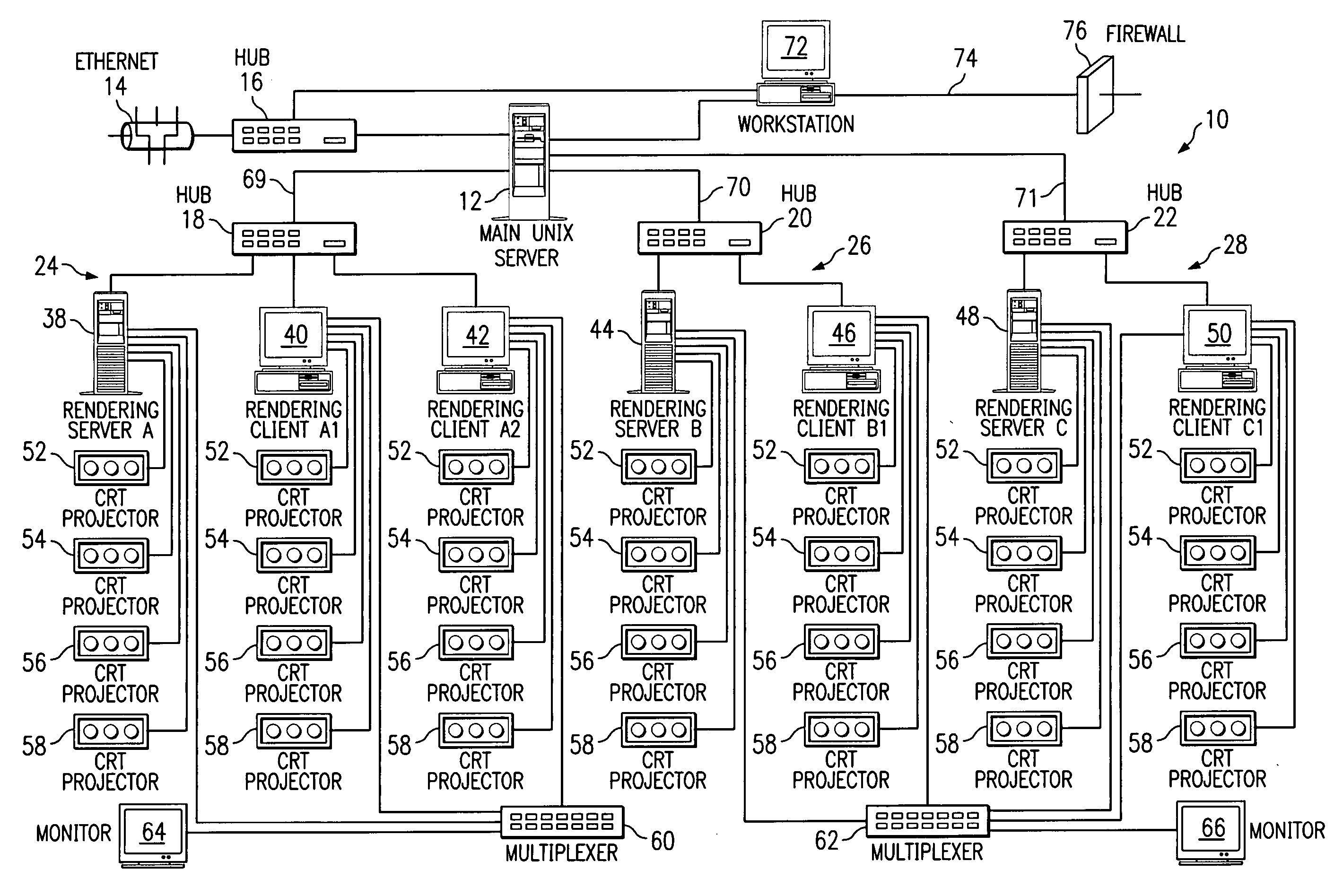
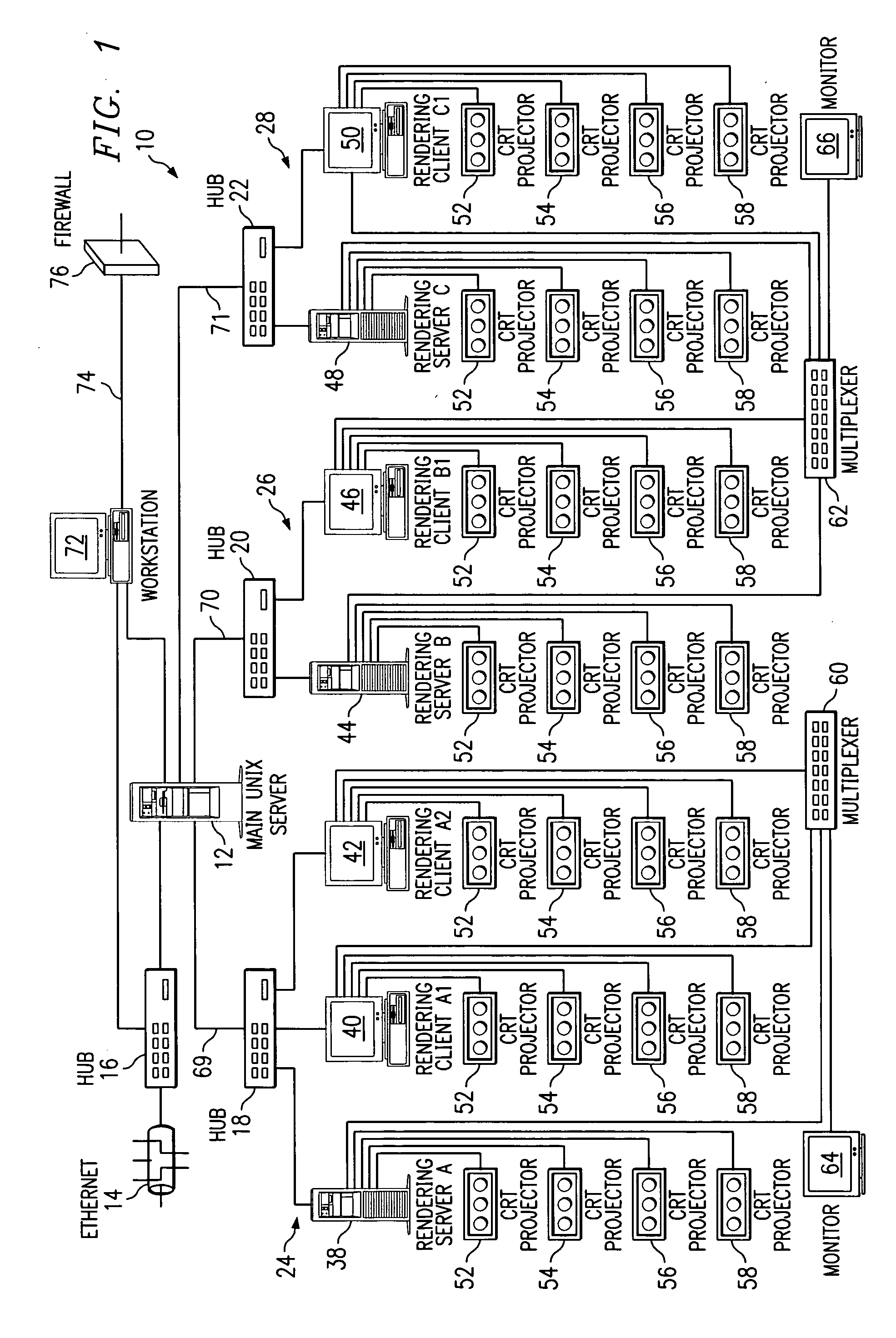
[0027]FIG. 1 illustrates a representative layout of a contiguous video projection array according to the invention, the illustrated embodiment being an airport terminal display system that displays animated graphics and a text data overlay from a flight information data system (FIDS) database. In FIG. 1, the video projection array system, indicated generally at 10, includes a main server 12 which accepts FIDS data or data from any other text source, such as may be presented in Oracle or SGL, through an internal Ethernet port 14 as joined by a high speed switching hub 16. The hub 16 makes it possible for multiple sourcing of the FIDS data for several isolated imaging arrays, only one such array 10 being shown in FIG. 1. The preferably UNIX-based main server 12 transceives data through a series of separate switching Ethernet hubs 18, 20 and 22. Each of the hubs 18-22 is directly linked to one or more groups 24-28 of imaging or rendering computers 38-50.

[0028] Each of the hubs 18-22 h...


PUM


Abstract

An autostereoscopic display system includes a lenticular lens display screen that projects a plurality of views of a scene from its front surface. A plurality of video projectors are disposed to the rear of the display screen and focus on a convergence point of the display screen's rear surface. Imaging computers drive the video projectors, each having a memory storing a scene to be displayed on the display screen. Each computer renders the scene from a preselected viewpoint that may be different from the viewpoints of the other imaging computers.

Description

RELATED APPLICATIONS [0001] This application is a division of U.S. patent application Ser. No. 09 / 921,090 filed Aug. 2, 2001, the specification of which is fully incorporated by reference herein.BACKGROUND OF THE INVENTION [0002] As display screens have grown in size and fineness of resolution, investigators have experimented with placing several such display screens adjacent to each other and causing three dimensional graphical data to be displayed on them. In 1992, the University of Illinois introduced a multi-user, room-sized immersive environment called the Pyramid CAVE (for “CAVE automatic virtual environment”). Three dimensional graphics were projected onto the walls and floors of a large cube composed of display screens, each typically measuring eight to ten feet. The cubic environment uses stereoscopic projection and spatialized sound to enhance immersion. Computers and display systems by Silicon Graphics, Inc. have created multi-panel displays which process three dimensiona...

Claims


Application Information

Patent Timeline
IPC IPC(8): G02B30/29G06T15/00H04N13/305H04N13/307
CPCG02B27/225G06T15/00G06T2200/16H04N13/0497H04N13/0285H04N13/0406H04N13/0459H04N13/0275H04N13/275H04N13/363H04N13/286H04N13/307H04N13/398H04N13/305G02B30/29G06T15/10
Inventor MARK, DAVIDWEICHERS, BRETT C.
Owner MARK RESOURCES
Learn More