Projection-type display apparatus

a display apparatus and projection-type technology, applied in the field of projection-type display apparatus, can solve the problems of flicker, difficult to secure a response of 5 msec or less with such a liquid crystal light valve, etc., and achieve the effect of stable stereoscopic display and easy installation

Active Publication Date: 2010-12-30
PANASONIC CORP
View PDF2 Cites 17 Cited by
  • Summary
  • Abstract
  • Description
  • Claims
  • Application Information

AI Technical Summary

Benefits of technology

[0014]With the projection-type display apparatus having the above configuration, it is possible to obtain continuously projection images for the right eye and for the left eye without switching image light using time division, and perform stereoscopic display with no flicker. Magnification projection is performed using one projection le

Problems solved by technology

Further, since an image for the right eye and an image for the left eye are switched by time division, a slow switching speed caus

Method used


Image

  • Projection-type display apparatus
  • Projection-type display apparatus
  • Projection-type display apparatus

Examples


embodiment 1

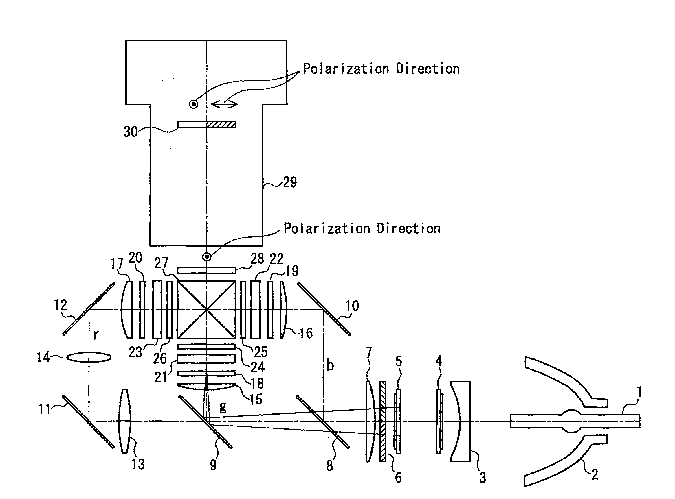
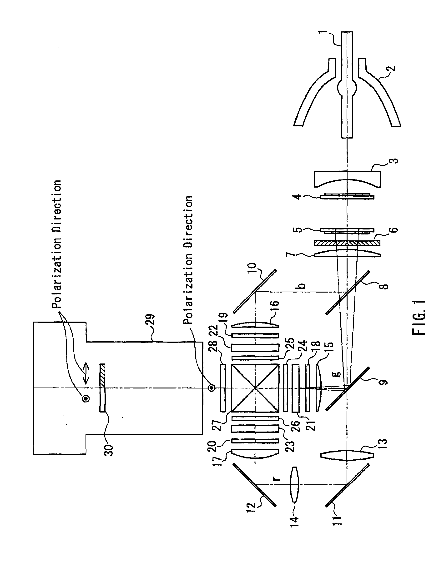
[0042]FIG. 1 is a plan view showing the configuration of a projection-type display apparatus according to Embodiment 1 of the present invention. Note that a part of the configuration is shown in cross section. A TN mode or VA mode transmission-type liquid crystal panel is used for each liquid crystal light valve.

[0043]A discharge lamp 1 is used as a light source, and is arranged inside a reflecting mirror 2. A concave lens 3 is arranged on the condensing side of the reflecting mirror 2, and on the exit side of the concave lens, an illumination optical system is arranged, which is constituted by first and second lens array plates 4 and 5, a polarization converting optical element 6, and a condensing lens 7.

[0044]An optical system on the exit side of the condensing lens 7 is constituted by a blue reflection dichroic mirror 8, a green reflection dichroic mirror 9, reflection mirrors 10, 11, and 12, relay lenses 13 and 14, field lenses 15, 16, and 17, incident side polarizing plates 18,...

embodiment 2

[0067]The overall configuration of a projection-type display apparatus according to Embodiment 2 of the present invention is shown in FIG. 6. In this projection-type display apparatus, a TN mode or VA mode transmission-type liquid crystal panel is used for each liquid crystal light valve.

[0068]This projection-type display apparatus basically has the same configuration as that of the projection-type display apparatus according to Embodiment 1 shown in FIG. 1. Therefore, the same reference numerals are given to the same elements, and a redundant description is omitted. The present embodiment differs from Embodiment 1 in the configuration of liquid crystal panels 50, 51, and 52. Below is a description of the configuration of the liquid crystal panels, and the operation thereof.

[0069]FIG. 7 is a cross-sectional view showing the planar configuration of the liquid crystal panels 50, 51, and 52. Each of the liquid crystal panels 50, 51, and 52 has pixels 55 having a matrix structure, and i...


PUM


Abstract

Provided are an illumination optical system allowing light beams to be condensed and enter an illumination area at different angles from each other, color separating elements that separate colors of the light beams from the illumination optical systems, liquid crystal light valves that modulate the color lights to form image light for the right and the left eyes, a color combining element that combines the color light beams, a wavelength-selective polarization rotating element that rotates the polarization direction of a predetermined color light so as to align the polarization direction with that of a light beam of another color, and a projection lens that magnifies and projects images. The liquid crystal light valves are provided with an incident side microlens array that causes the light beams for the right and the left eyes to pass respectively through the right and the left eye image pixels, and an exit side microlens array that condenses the light that has passed through the pixels. The projection lens is provided with a polarized light separating element that causes the polarization directions of image light for the right and the left eyes to be orthogonal to each other. Using one projection-type display apparatus, a highly efficient stereoscopic image can be displayed with little flicker and cross talk of image light for the right eye and for the left eye.

Description

BACKGROUND OF THE INVENTION[0001]1. Field of the Invention[0002]The present invention relates to a projection-type display apparatus that irradiates an image formed on a light valve with illumination light, and magnifies and projects the image on a screen using a projection lens, and in particular relates to a projection-type display apparatus for stereoscopic display.[0003]2. Description of Related Art[0004]JP 2005-65055A, for example, discloses that a video display apparatus for stereoscopic display is composed of one projection-type display apparatus that uses liquid crystal panels for light valves, aiming to make the apparatus small and easy to be installed, and enabling stable stereoscopic display images to be obtained. This conventional projection-type display apparatus is shown in FIG. 11.[0005]An optical system 100 that forms blue, green, and red light images is constituted by a light source lamp 101, dichroic mirrors 102 and 103 for color separation, reflection mirrors 104 ...

Claims


Application Information

Patent Timeline
IPC IPC(8): G02F1/13363G02B27/26G02B30/25H04N13/363
CPCG02B27/26G02B27/283H04N13/0459H04N13/0422H04N13/0434G03B21/00G03B21/006H04N13/337H04N13/324H04N13/363G02B30/25
Inventor TANAKA, TAKAAKI
Owner PANASONIC CORP
Why Eureka
Try Eureka