
Light source device, projection apparatus, and projection method

a technology of projection apparatus and light source device, which is applied in the direction of static indicating device, instruments, optics, etc., can solve the problems of insufficient red luminance, reduced size, weight or cost of the entire device, and reduced light emission efficiency of red phosphors

Active Publication Date: 2010-12-30
CASIO COMPUTER CO LTD
View PDF1 Cites 73 Cited by
  • Summary
  • Abstract
  • Description
  • Claims
  • Application Information

AI Technical Summary

Benefits of technology

[0009]According to one aspect of the present invention, there is provided a light source device comprising: a first light source configured to emit light within a first wavelength band; a light-source light production section configured to sequentially produce light-source light of a plurality of colors at predetermined frequency by using light emitted by the first light source; a second light source configured to emit light within a second wavelength band different from the first wavelength band; and a light source control section configured to control drive timing for each of the first and second light sources such that a light emission period for light-source light using light emitted by the second light source is positioned between light emission periods for the light-source light of the plurality of colors produced by the light-source light production section and that the light-source light using light emitted by the second light source has a frequency higher than that of the light-source light production section.

Problems solved by technology

Therefore, the increase in the number of parts hinders reduction in the size, weight, or cost of the entire device.
However, when the invention described in Jpn. Pat. Appin. KOKAI Publication No. 2004-341105 mentioned above is adopted, the presently known various red phosphors are significantly lower in light emission efficiency, compared to green and blue phosphors, resulting in inadequate red luminance.
When a brighter projected image is formed by giving priority to luminance, white balance is lost, with the result that color reproducibility degrades.
Conversely, giving priority to white balance and hence color reproducibility decreases the overall luminance of a projected image because of the low luminance of the red image, resulting in a dark image.

Method used


Image

  • Light source device, projection apparatus, and projection method
  • Light source device, projection apparatus, and projection method
  • Light source device, projection apparatus, and projection method

Examples


modified example

[0073]Next, another example of the configuration of the color wheel 24 will be described.

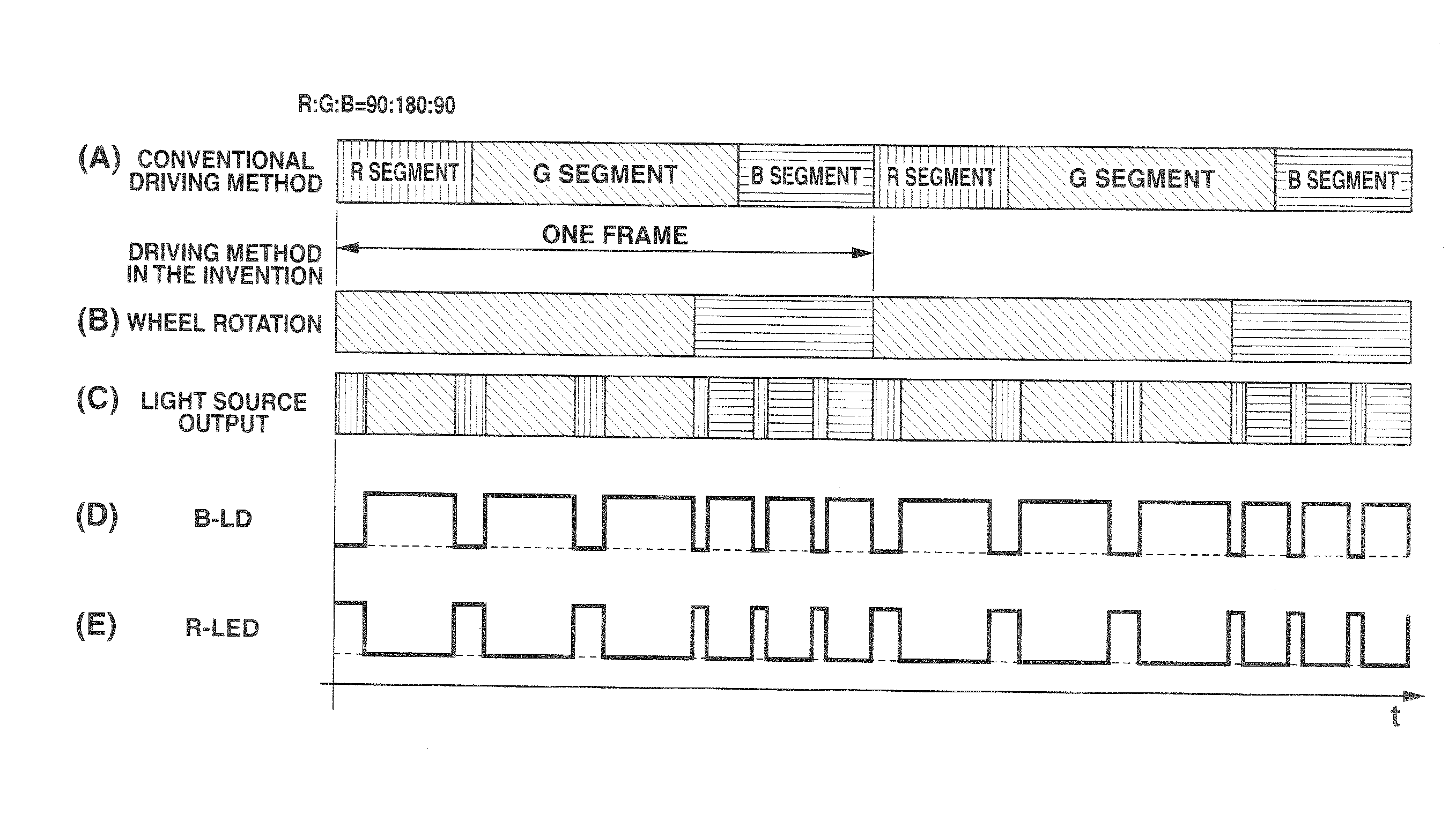
[0074]FIG. 5 shows the configuration of a color wheel 24′ different from the color wheel 24. As shown in FIG. 5, on the color wheel 24′, a green phosphor reflective plate 24G with a central angle of 240° and a blue diffusing plate 24B with a central angle of 120° form one ring so that the green phosphor reflective plate 24G and the blue diffusing plate 24B have a ratio of 2:1.

[0075]The wavelength of blue laser light emitted by each of the semiconductor lasers 20A to 20C, the wavelength of green light excited by the green phosphor reflective plate 24G of the color wheel 24′ illuminated by the blue laser light, and the wavelength of red light produced by the LED 21 are the same as those described above.

[0076]An operation involving this color wheel 24′ will now be discussed.

[0077]In this case, the time ratio at which the R, G, and B primary color images composing one frame of a color image to be pr...


PUM


Abstract

A light source device includes a first light source configured to emit light within a first wavelength band, a light-source light production section configured to sequentially produce light-source light of a plurality of colors at predetermined frequency by using light emitted by the first light source, a second light source configured to emit light within a second wavelength band different from the first wavelength band, and a light source control section configured to control drive timing for each of the first and second light sources such that a light emission period for light-source light using light emitted by the second light source is positioned between light emission periods for the light-source light of the plurality of colors produced by the light-source light production section and that the light-source light using light emitted by the second light source has a frequency higher than that of the light-source light production section.

Description

CROSS-REFERENCE TO RELATED APPLICATIONS[0001]This application is based'upon and claims the benefit of priority from prior Japanese Patent Application No. 2009-156092, filed Jun. 30, 2009, the entire contents of which are incorporated herein by reference.BACKGROUND OF THE INVENTION[0002]1. Field of the Invention[0003]The present invention relates to a light source device, a projection apparatus, and a projection method that are suitable for a Digital Light Processing (DLP [registered trademark]) data projector apparatus and the like.[0004]2. Description of the Related Art[0005]Displaying colors with a projection display apparatus requires planar light sources that emit the primary colors of red, green, and blue, and spatial optical modulators corresponding to the primary colors. Therefore, the increase in the number of parts hinders reduction in the size, weight, or cost of the entire device. For example, Jpn. Pat. Appln. KOKAI Publication No. 2004-341105 discloses the technology in ...

Claims


Application Information

Patent Timeline
Patent Type & Authority Applications(United States)
IPC IPC(8): G03B21/14H05B41/16
CPCH04N9/3114H04N9/3155H04N9/3164H04N9/3197G03B33/08H05B37/02G03B21/2013G03B21/204G09G3/22H05B47/10H05B47/165
Inventor MIYAZAKI, TAKESHI
Owner CASIO COMPUTER CO LTD
Features
  • Generate Ideas
  • Intellectual Property
  • Life Sciences
  • Materials
  • Tech Scout
  • Unparalleled Data Quality
  • Higher Quality Content
  • 60% Fewer Hallucinations
Learn More