Sensor function for controlling at a variable transmission frequency for the purpose of detecting contamination

a technology of transmission frequency and vibration sensor, which is applied in the direction of instruments, structural/machine measurement, and reradiation, etc., can solve the problem of resonant frequency deviating from the original uninfluenced resonant frequency of harmonic oscillator

Active Publication Date: 2010-12-30
ROBERT BOSCH GMBH
View PDF4 Cites 12 Cited by
  • Summary
  • Abstract
  • Description
  • Claims
  • Application Information

AI Technical Summary

Benefits of technology

[0015]The core of the present invention is the realization of a sensor self-test function, which makes it possible to excite the vibration sensor into periodic vibrations at various frequencies, and to perform an analysis of the post-vibration process as a function of the excitation frequency.

Problems solved by technology

As already mentioned, the resonant frequency of a harmonic oscillator behaves in a manner that is inversely proportional to the radical of its mass, which means that additional mass components such as contamination or ice on the vibration sensor, for example, cause detuning of the harmonic oscillator (vibration component), and the resulting resonant frequency consequently deviates from the originally uninfluenced resonant frequency of the harmonic oscillator.

Method used


Image

  • Sensor function for controlling at a variable transmission frequency for the purpose of detecting contamination
  • Sensor function for controlling at a variable transmission frequency for the purpose of detecting contamination
  • Sensor function for controlling at a variable transmission frequency for the purpose of detecting contamination

Examples


Embodiment Construction

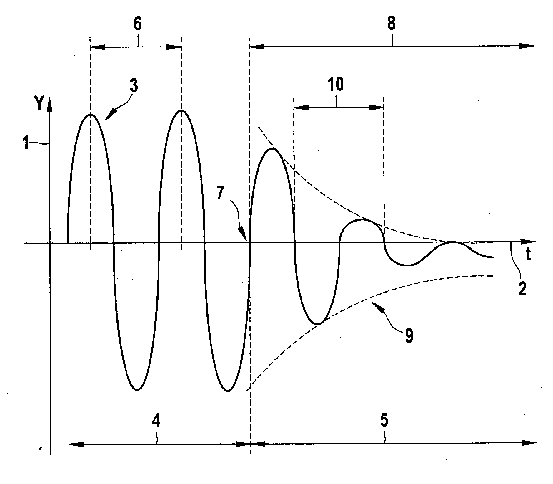
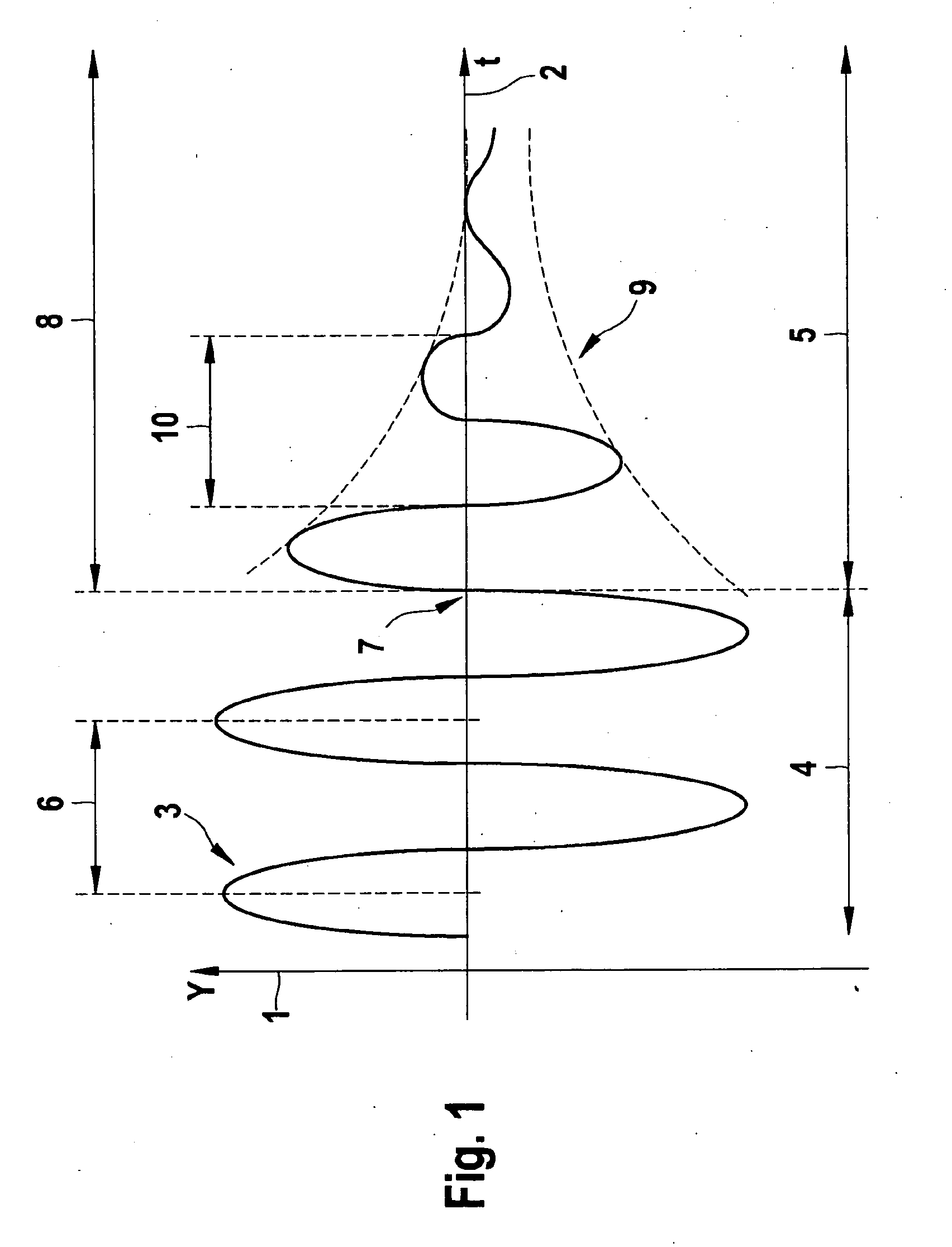
[0024]FIG. 1 shows the amplitude time characteristic of a vibration pulse of a vibration component of the vibration sensor, in which deflection Y of the vibration component from its neutral position (1) has been plotted over time axis (2) as signal characteristic (3). The amplitude time characteristic is subdivided into the regions of the excitation (4) and the region of the post-vibration process (5). The vibration component is excited by a periodic excitation signal having period duration (6) for the forced vibration at a given unvarying amplitude. In the process, the harmonic oscillator, i.e., the vibration component, vibrates at the frequency of the excitation signal (reciprocal value of the period duration of the excitation) and thus executes a damped mechanical vibration.

[0025]After the excitation signal has been switched off, i.e., at instant (7), the harmonic oscillator vibrates freely. Because of the provided damping, the vibration amplitude decreases along region (8) durin...


PUM


Abstract

In a method for functional testing of a mechanical vibration sensor, a vibration signal is generated on the vibration component of the vibration sensor with the aid of a periodic excitation signal, the frequency of which excitation signal is varied, and a post-vibration process of the vibration component of the vibration sensor is analyzed once the excitation signal has been switched off.

Description

BACKGROUND OF THE INVENTION[0001]1. Field of the Invention[0002]The present invention relates to a method for functional testing of a mechanical vibration sensor, and to a measuring system for detecting obstacles on a motor vehicle having functional testing.[0003]2. Description of Related Art[0004]Sensor systems for measuring the distance of obstacles, particularly with the aid of ultrasonic sensors, are known from published German patent document DE 10 2005 057 973 and also from U.S. Pat. No. 6,040,765, for instance. In such systems the sensor generates a sound pulse which travels away from the sensor at the propagation rate of the particular medium (usually air), is reflected by an obstacle, and the reflection is then detected by the sensor, whereupon the distance to the obstacle is able to be calculated from the resulting propagation time and the known propagation rate. This distance measurement according to the so-called pulse-echo method requires a periodic excitation of a vibr...

Claims


Application Information

Patent Timeline
Patent Type & Authority Applications(United States)
IPC IPC(8): G01S15/00G01V13/00G01S15/931
CPCG01S15/931G01S7/52004
Inventor FRANK, MICHAELPREISSLER, PETER
Owner ROBERT BOSCH GMBH
Why Eureka
Try Eureka