
Augmented Surface Sensor for Measuring Flow Velocity

a technology of flow velocity and augmented surface, which is applied in the direction of volume/mass flow measurement, measurement devices, instruments, etc., can solve the problems of changing flow grade or flow geometry, monitoring velocity at the discharge point into the manhole, and worse than ill advised in the discharge point from the manhole or the discharge pipe, so as to achieve the effect of minimizing entry into confined spa

Active Publication Date: 2011-01-06
ADS
View PDF38 Cites 28 Cited by
  • Summary
  • Abstract
  • Description
  • Claims
  • Application Information

AI Technical Summary

Benefits of technology

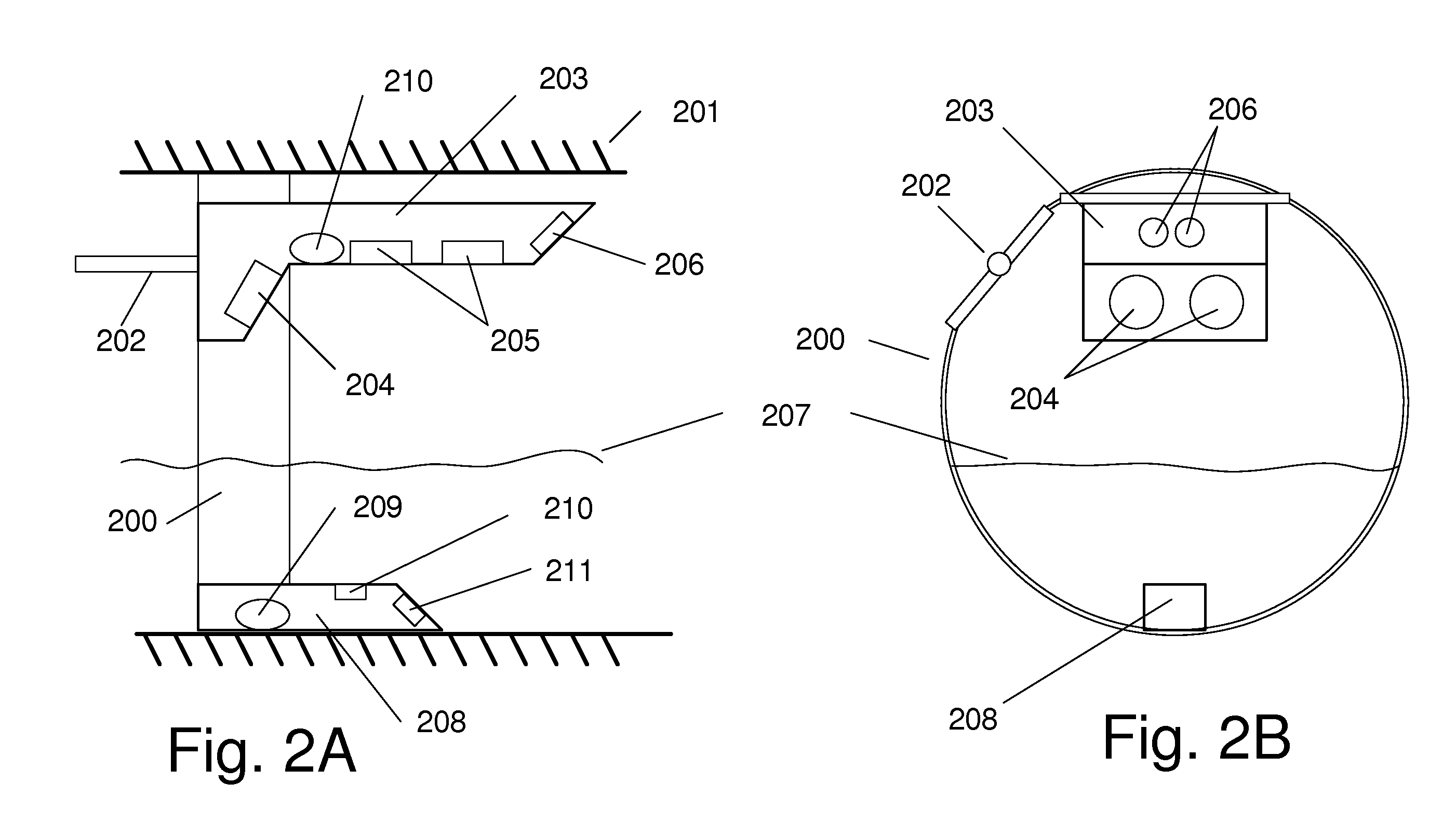
[0014]As a further benefit, the small size of the sensor head and the separate remotely located electronics package further allow the sensor to be mounted inside small pipes with minimal effect on the flow.

Problems solved by technology

Monitoring velocity at the discharge point into the manhole, in the manhole itself, in the discharge point from the manhole or in the discharge pipe is worse than ill advised as these points do not have stable hydraulics.
Small pipes are pipes that are small relative to the man hole access chamber potentially causing a change in flow grade or flow geometry as the flow transitions from the influent pipe to the man hole and back again to the exit pipe.

Method used


Image

  • Augmented Surface Sensor for Measuring Flow Velocity
  • Augmented Surface Sensor for Measuring Flow Velocity
  • Augmented Surface Sensor for Measuring Flow Velocity

Examples


Embodiment Construction

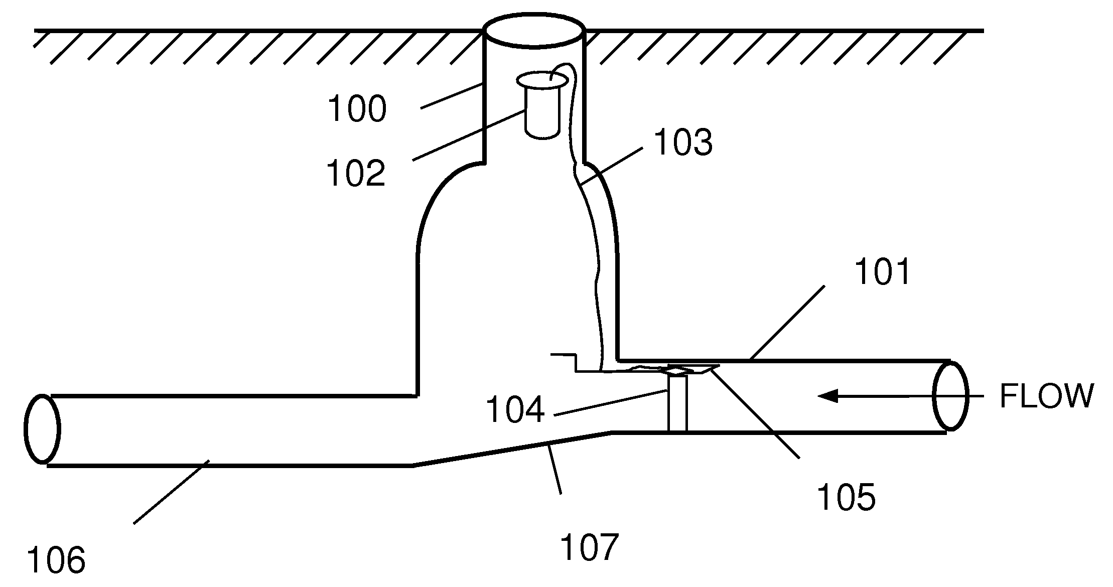
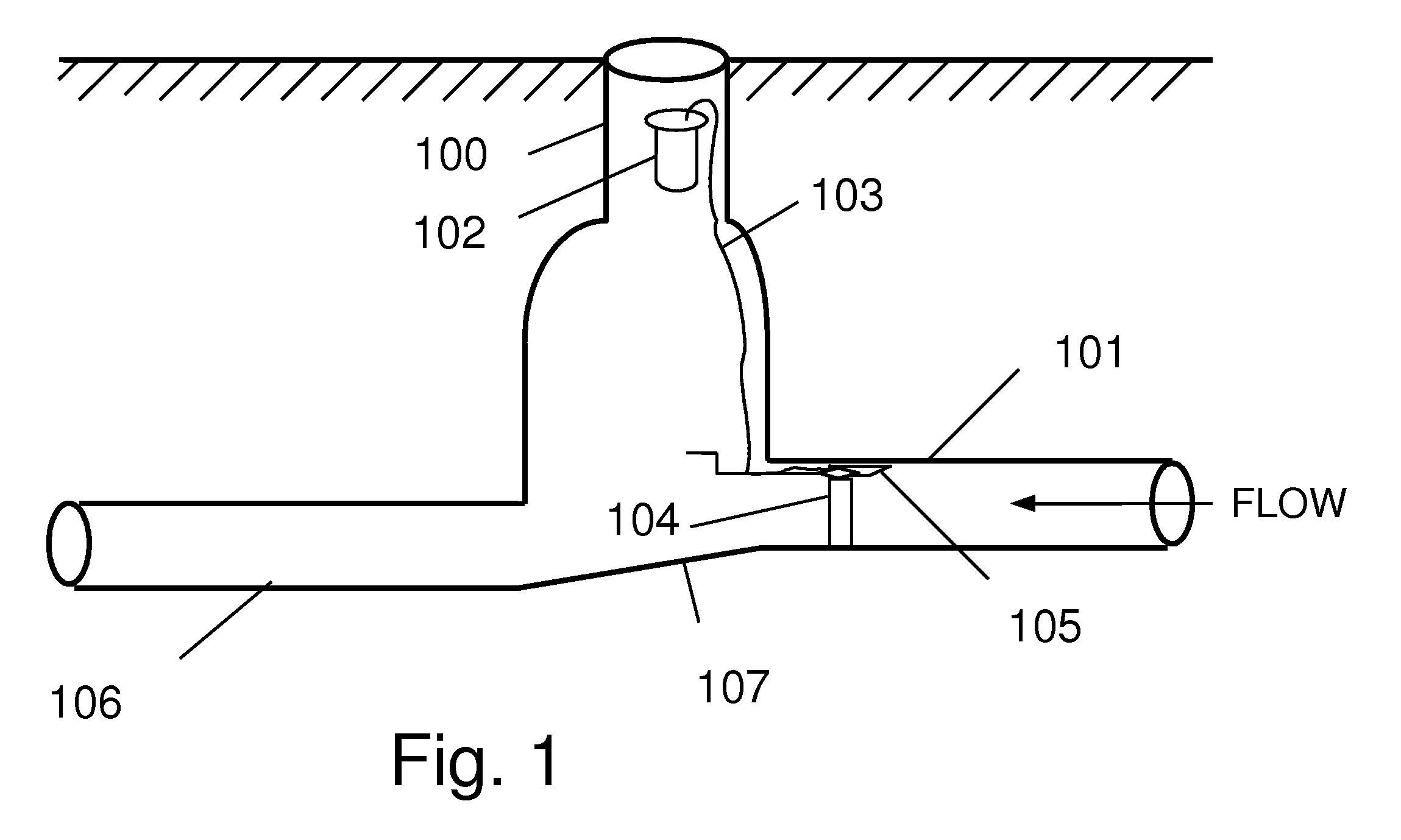
[0027]The present invention is particularly well adapted for measuring flows in small pipes, typically less than or equal to 24 inches in diameter. Small pipes are pipes that are small relative to the man hole access chamber potentially causing a change in flow grade or flow geometry as the flow transitions from the influent pipe to the man hole and back again to the exit pipe. The sensor assembly is adapted to measure steady state flow in the pipe, without disturbing the flow, and is preferably positioned upstream from the opening of the pipe, away from flow disturbances caused by the pipe opening into the man hole space.

[0028]Fast shallow flows potentially present challenges for accurate measurement. Fast flows around a sensor produce a Bernoulli effect that causes pressure / level sensors to read incorrectly. Fast flows over the sensor cause hydraulic jumps. These jumps increase the depth directly over the sensor (where depth is measured), but not in front of the sensor (where the ...


PUM


Abstract

A system and method for measurement of flow parameters in a sewer pipe that may be partially or completely filled. Flow parameters may include flow velocity, flow volume, depth of flow and surcharge pressure. Measurements are taken from a sensor head installed on the inside of the pipe at the top of the pipe approximately the larger of at least 1 foot or 1 pipe diameter upstream of a pipe opening. Flow velocity may be measured by two different technologies. The technology employed depends on whether or not the pipe is full. If the pipe is not full then flow velocity may be measured, for example, using a wide beam, ultrasonic, diagonally downward looking Doppler signal that interacts with the surface of the flow. If the pipe is full, then flow velocity may be measured using, for example, an average velocity Doppler sensor, a peak velocity Doppler sensor or an ultrasonic velocity profiler.

Description

RELATED APPLICATIONS[0001]This application is an application claiming the benefit under 35 USC 119(e) of prior U.S. Provisional Application 61 / 222,997, titled “Open Channel Meter for Measuring Velocity”, filed Jul. 3, 2009 by Petroff, and U.S. Provisional Application 61,319,847, titled “Open Channel Meter for Measuring Velocity”, filed Mar. 31, 2010 by Petroff et al., both of which are hereby incorporated herein by reference in their entirety.BACKGROUND[0002]1. Field of the Invention[0003]The present invention pertains generally to the field of measurement of water flowing in partially and completely full pipes using a sensor that is not in contact with the flow, more particularly, to the class of devices that utilize ultrasonic energy to determine the channel velocity.[0004]2. Background of the Invention[0005]There are many cases where it is important to measure the rate of flow in a pipe. For example, one may need to know the flow rate to determine a billing rate between two commu...

Claims


Application Information

Patent Timeline
Patent Type & Authority Applications(United States)
IPC IPC(8): G01F1/66
CPCG01F1/662G01F1/667G01F1/663
Inventor PETROFF, ALAN
Owner ADS
Learn More