Image recording apparatus with jet and suction

a technology of image recording and suction, which is applied in the direction of recording apparatus, photomechanical apparatus, instruments, etc., can solve the problems of inability to place the suction opening adjacent to the drum, inability to completely or efficiently suction gas generated from the photosensitive material, and inability to clean up the interior of the exposure head, etc., to achieve the effect of minimizing the entry of the exposure head

Inactive Publication Date: 2007-06-12
DAINIPPON SCREEN MTG CO LTD
View PDF9 Cites 9 Cited by
  • Summary
  • Abstract
  • Description
  • Claims
  • Application Information

AI Technical Summary

Benefits of technology

[0007]The object of this invention, therefore, is to provide an image recording apparatus for recording images by emitting laser light to a photosensitive material and vaporizing components of the photosensitive material as a gas from the surface of the photosensitive material, which apparatus effectively minimizes entry to an exposure head of the gas generated from the photosensitive material.
[0012]With this image recording apparatus, the gas generated from the surface of the photosensitive material by irradiation of a light beam such as laser light may be sucked with increased efficiency. This minimizes the chance of entry to the exposure head of the gas generated from the surface of the photosensitive material.

Problems solved by technology

However, where such an apparatus uses a clamp mechanism for clamping an end of a printing plate, as a device for mounting the printing plate peripherally of a rotatable drum, it is difficult to place the suction opening adjacent the drum since the clamp mechanism has a certain size.
Actually, however, the gas generated from the photosensitive material is not sucked completely or efficiently.
Consequently, when images are recorded on the photosensitive material continuously for a long time, the gas generated from the photosensitive material inevitably enters the exposure head to contaminate the interior of the exposure head.

Method used


Image

  • Image recording apparatus with jet and suction
  • Image recording apparatus with jet and suction
  • Image recording apparatus with jet and suction

Examples


first embodiment

[0044]this invention will be described hereinafter with reference to the image recordings.

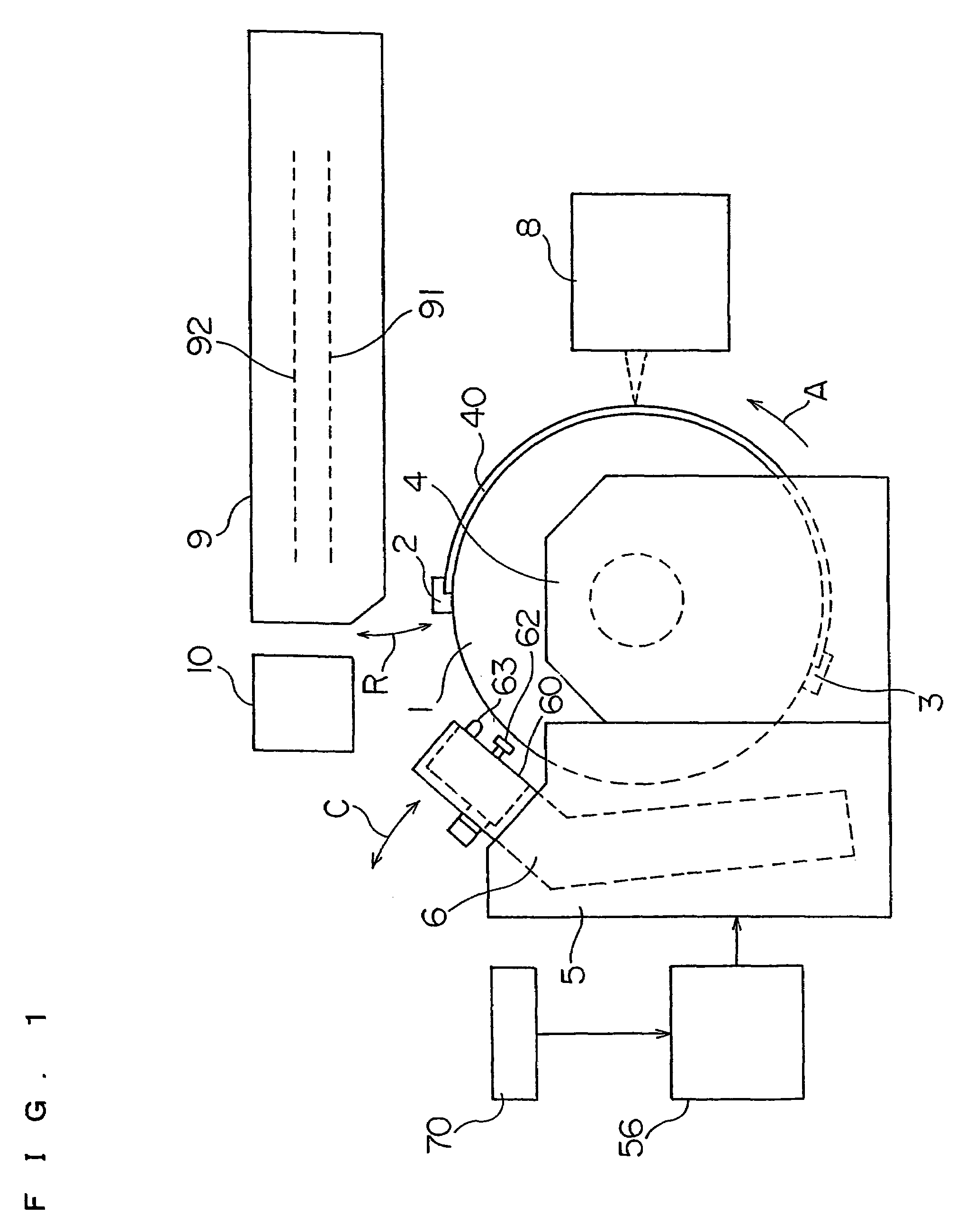
[0045]FIG. 1 is a schematic side view of an image recording apparatus in the first embodiment of this invention. FIG. 2 is a schematic front view of the image recording apparatus.

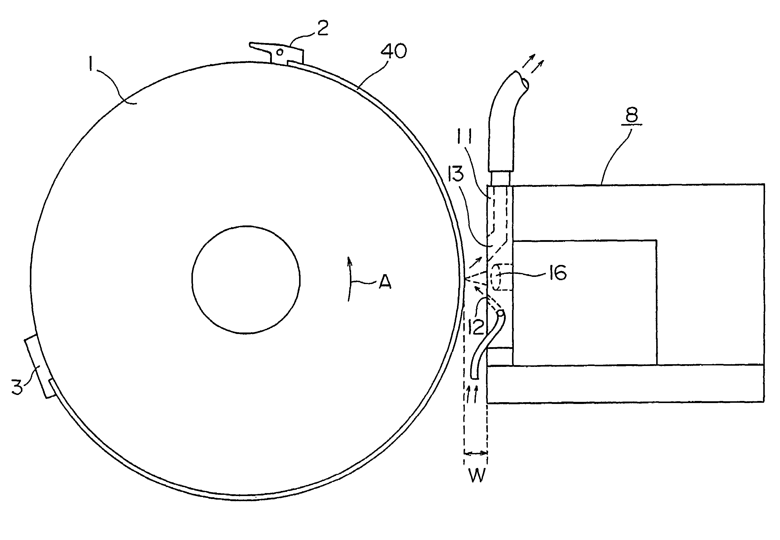
[0046]Referring to FIGS. 1 and 2, the image recording apparatus includes a cylindrical recording drum 1. The recording drum 1 is driven by a drive device 4 to rotate in a direction of arrow A (main scanning direction) about a rotary shaft 1a. The recording drum 1 holds an aluminum printing plate 40 mounted peripherally thereof as a photosensitive material. An end of the printing plate 40 is fixed to the peripheral surface of the recording drum 1 by a plurality of forward end clamps 2. The other end of the printing plate 40 is fixed to the peripheral surface of the recording drum 1 by a plurality of rear end clamps 3.

[0047]An exposure head 8 with a plurality of laser diodes is disposed forwardly of the recording drum 1....

second embodiment

[0101]this invention will be described next with reference to the image recordings.

[0102]FIG. 14 is a perspective view of an image recording apparatus in the second embodiment of the invention. The image recording apparatus in the second embodiment has a housing 100. The apparatus includes, arranged inside the housing 100, a base 111, a recording drum 110 rotatably supported by a pair of bearings 112 formed on the base 111, a motor 113 for rotating the recording drum 110, an exposure head 108 mounted on the base 111 to be movable along an axis of rotation of the recording drum 110, a signal cable (not shown) for supplying image signals to the exposure head 108, a power cable (not shown) for supplying power to the exposure head 108, a jet pipe 173 to be described in detail hereinafter, an exhaust pipe 177 described in detail hereinafter, a cable bearer 114 for guiding the jet pipe 173 and exhaust pipe 177, a jet pump 170, and an exhaust pump 179.

[0103]The recording drum 110 of the im...


PUM

PropertyMeasurementUnit
angleaaaaaaaaaa
velocityaaaaaaaaaa
distanceaaaaaaaaaa

Abstract

A gas is generated from a printing plate by exposure of the printing plate. A gas diffusing suction unit jets air from air jet ports to diffuse the gas generated from the printing plate by irradiation of laser light. The gas diffused by the air is sucked along with the air from a gas suction opening of the gas diffusing suction unit. At this time, a gas suction velocity is set to 1.2 or more times an air jet velocity to suck the gas / air efficiently. The gas / air may be sucked efficiently by setting a volume of suction to 30 or more times a volume of air jet.

Description

BACKGROUND OF THE INVENTION[0001]1. Field of the Invention[0002]This invention relates to an image recording apparatus for recording images on a photosensitive material mounted peripherally of a drum.[0003]2. Description of the Related Art[0004]In an image recording apparatus for recording images by emitting laser light to a photosensitive material and vaporizing components of the photosensitive material as a gas from the surface of the photosensitive material, the gas generated from the photosensitive material enters the exposure head and contaminates the interior of the exposure head. Thus, an image recording apparatus with a gas suction device has been proposed as described in Japanese Patent No. 2886087.[0005]It is well known that such an image recording apparatus can achieve an improved gas suction efficiency with a gas suction opening disposed adjacent the surface of the photosensitive material.[0006]However, where such an apparatus uses a clamp mechanism for clamping an end o...

Claims


Application Information

Patent Timeline
Patent Type & Authority Patents(United States)
IPC IPC(8): B41J2/435B41J2/165G03F7/24
CPCG03F7/24
Inventor IWASA, HIROSHIMATSUURA, HIDEKI
Owner DAINIPPON SCREEN MTG CO LTD
Why Eureka
Try Eureka