Powder handling device

Inactive Publication Date: 2009-12-10
POWDER PROJECTS
View PDF15 Cites 10 Cited by
  • Summary
  • Abstract
  • Description
  • Claims
  • Application Information

AI Technical Summary

Benefits of technology

[0143]In the preferred embodiment of the current invention the bag is cut by the blade after the application of positive pressure. This allows full benefit of the fluidisation of the milk powder to be gained. These benefits include an increased yield of released milk powder from the bag and minimises entry of foreign matter into the milk powder.
[0144]In a preferred embodiment, fluidisation is provided via the spear before the bag is cut open, then after the bag is cut and the bag pressure h

Problems solved by technology

This leads to a large number of bags which have to be opened and emptied before the material can be used.
Most existing or conventional methods for emptying bags of powdered material involve a large amount of manual labour.
As well as being time consuming, one major disadvantage of this method is that the operator may come into contact with the powdered material.
This is a significant problem for sanitary reasons as contact between the powdered material and the operator or external environments can create bacterial and foreign contamination problems.
However when done manually this can be difficult and it is impossible to guarantee that skin contact will not be made with the powder.
Even the handler wearing gloves to prevent skin contact with the powder may not overcome this problem.
Other contamination from the environment can also occur.
These contaminants may include old powder from previous use of the tipping station due to inadequate cleaning, broken knife blades, or parts thereof from cutting open the bags, or bacterial or other matter in the air/environment.
Manually emptying bags of powdered material can also result in decreased yield, due to powder being left behind in pockets or comers of the bag.
This may especially be the case if the operator is careless during the emptying process.
If the powder is of high value as is the case with dairy powders, or a large number of bags are being emptied in a careless manner, this can lead to a considerably decreased yield.
The long term results may be increased costs or decreased profits for the company.
One significant disadvantage of this method is that the rotating knives are indiscriminate in terms of cutting the bags.
Th

Method used


Image

  • Powder handling device
  • Powder handling device
  • Powder handling device

Examples


Embodiment Construction

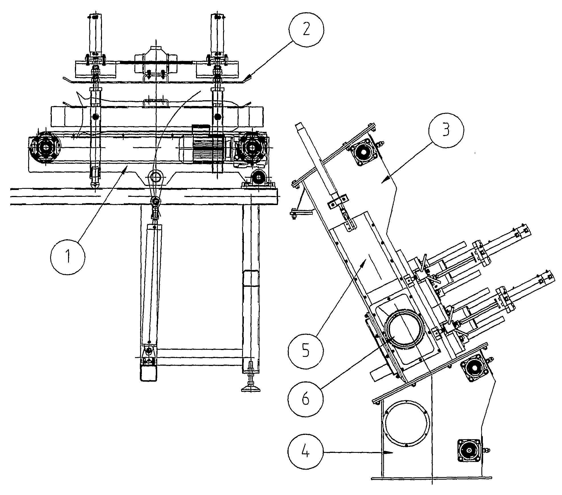
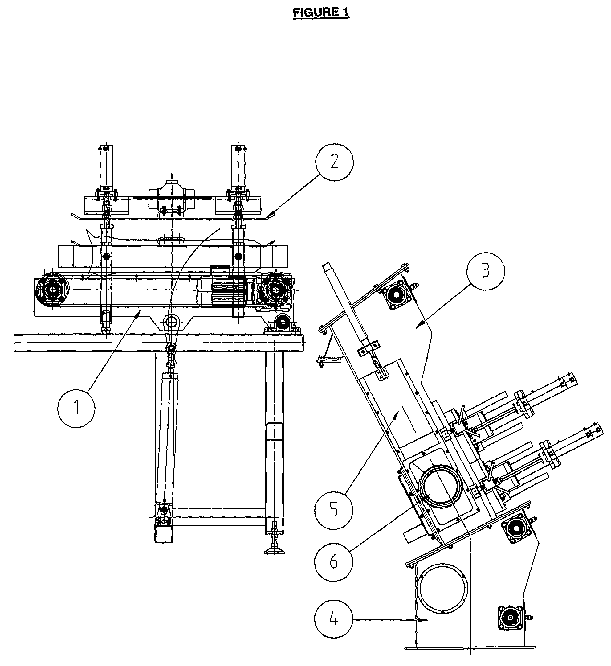
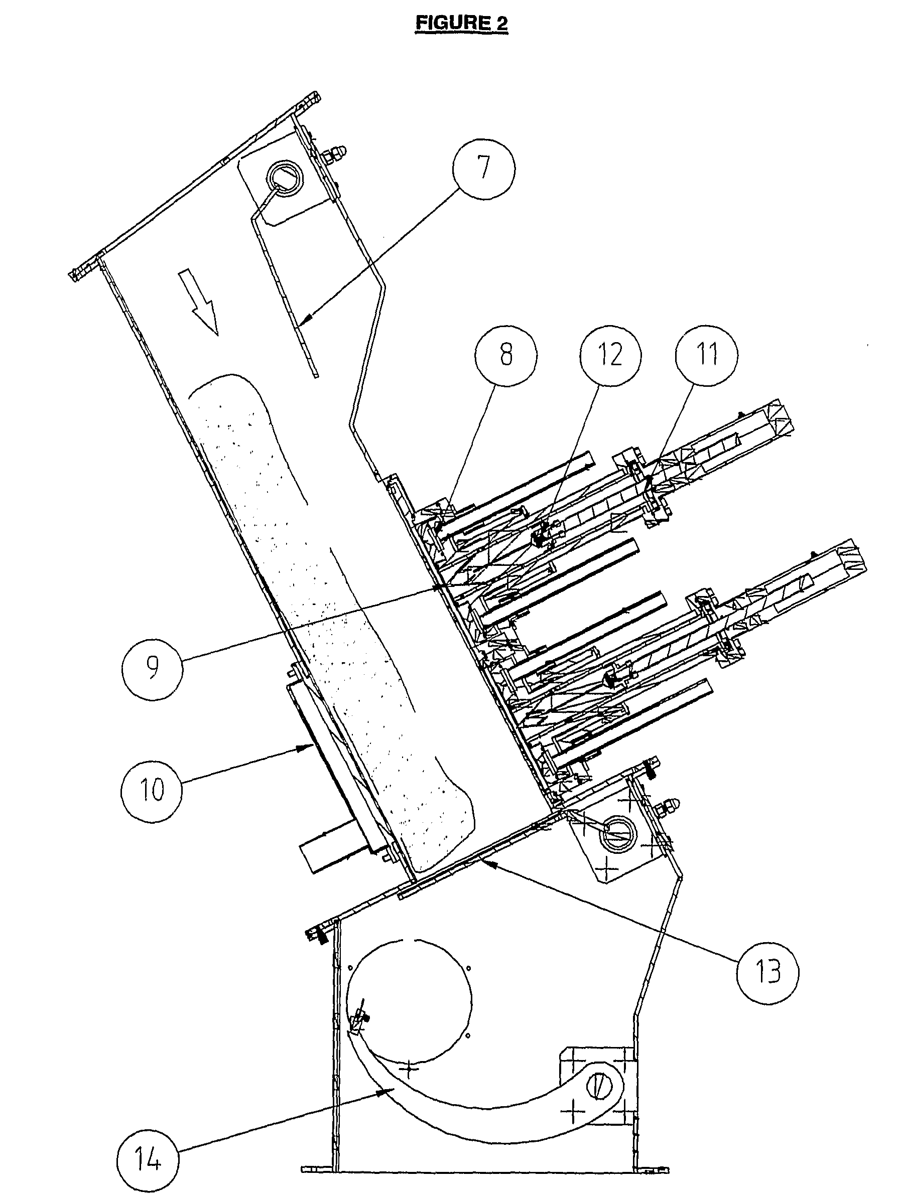
[0217]With reference to the figures above, the first section is a bag infeed conveyor (1) which moves the bag onto a bag clamping plate (2). The bag clamp plate is lowered while the conveyor is tilted in position. The bag clamp plate (2) is raised and with the bag entry door open (7), the bag is fed into the main chamber (3).

[0218]The chamber (3) is sealed and is designed to prevent the introduction of foreign matter into the flowable material. Entry to the sealed chamber (3) is by way of an entry door (7).

[0219]Once the bag is in the sealed chamber (3), the entry door (7) will close. Beneath the bag is a bag holding door (13). This bag holding door (13) serves a two fold purpose. Firstly, in the closed position the flap supports the bag as it moves into position. Secondly, the bag holding door (13) in the open position serves as a control point to prevent the back flow of milk powder into the sealed chamber (3).

[0220]Once the receptacle is in position, a vacuum is applied to both f...


PUM


Abstract

A method for releasing flowable material via an automated means from a receptacle which has at least one closed end, characterised by the steps of locating the receptacle in a defined position relative to a receptacle opening mechanism, and opening the receptacle with the receptacle opening mechanism, the method characterised in that the receptacle is positioned such that it is opened substantially below the bulk of the material in the receptacle. Also disclosed is a method of releasing flowable material via an automated means from a receptacle which has at least one closed end, characterised by the steps of locating the receptacle in a defined position relative to a receptacle opening mechanism, and opening the receptacle with the receptacle opening mechanism, the method characterised in that the flowable material within the receptacle is fluidised.

Description

TECHNICAL FIELD[0001]This invention relates to a device for emptying bags of powder.BACKGROUND ART[0002]Many companies and industries make use of particulate matter which is usually supplied in bags of volumes which range from 25 kilograms to 50 kilograms.[0003]One main industry which uses a large number of bags containing particulate matter (specifically powdered material) is the dairy industry. An estimated fifty million, twenty five kilogram bags of milk powder or milk powder derivatives are exported from New Zealand annually.[0004]Similarly large numbers of bags are transported around New Zealand. This leads to a large number of bags which have to be opened and emptied before the material can be used.[0005]Most existing or conventional methods for emptying bags of powdered material involve a large amount of manual labour. This varies on the type of bag which is used, however in most instances it involves a person lifting a bag off a pallet, removing the outer Kraft paper from th...

Claims


Application Information

Patent Timeline
IPC IPC(8): B65G53/40B65G53/52
CPCB65B69/0008B65B69/0033B65B69/0041B65G65/23B65G65/40B65G69/001B65G69/06
Inventor DANCE, JEFFERY ROBERTMILES, RICHARD JOHN
Owner POWDER PROJECTS
Why Eureka
Try Eureka