Seal structure, method of forming seal structure, wire body, and electronic apparatus

a technology of sealing structure and sealing wire, which is applied in the direction of electrical apparatus construction details, electrical apparatus casings/cabinets/drawers, gaseous cathodes, etc., can solve the problems of increasing cost and difficulty in placing the gasket in such a small gap, and achieve the effect of low cos

Active Publication Date: 2011-01-06
SUMITOMO ELECTRIC IND LTD
View PDF4 Cites 15 Cited by
  • Summary
  • Abstract
  • Description
  • Claims
  • Application Information

AI Technical Summary

Benefits of technology

[0030]The seal structure, the wire body and the electronic apparatus of the present invention can provide a waterproof structure at low cost while flexibly adapting to design change of the wire member. Further, the waterproof structure can also be placed in a narrow space.

Problems solved by technology

First, a mold or the like is required for integrally forming the protrusion (50) and the FPC (30). Then, each time the FPC design is changed, a new injection mold becomes necessary, leading to increase in cost.
Second, because of the need for integration with the FPC (30), the material for the rubber-like elastic body of which the gasket (10) is formed has to be selected from limited alternatives.
Third, there is a case where in a narrow space between two housings in an electronic apparatus such as the space of a slide portion of a slide-type mobile terminal, the housings and a wire member have to be sealed. If the above-described gasket structure is applied to this case, because of a considerably large dimension of the height of the whole gasket, it is difficult to place the gasket in such a small gap.

Method used


Image

  • Seal structure, method of forming seal structure, wire body, and electronic apparatus
  • Seal structure, method of forming seal structure, wire body, and electronic apparatus
  • Seal structure, method of forming seal structure, wire body, and electronic apparatus

Examples


first embodiment

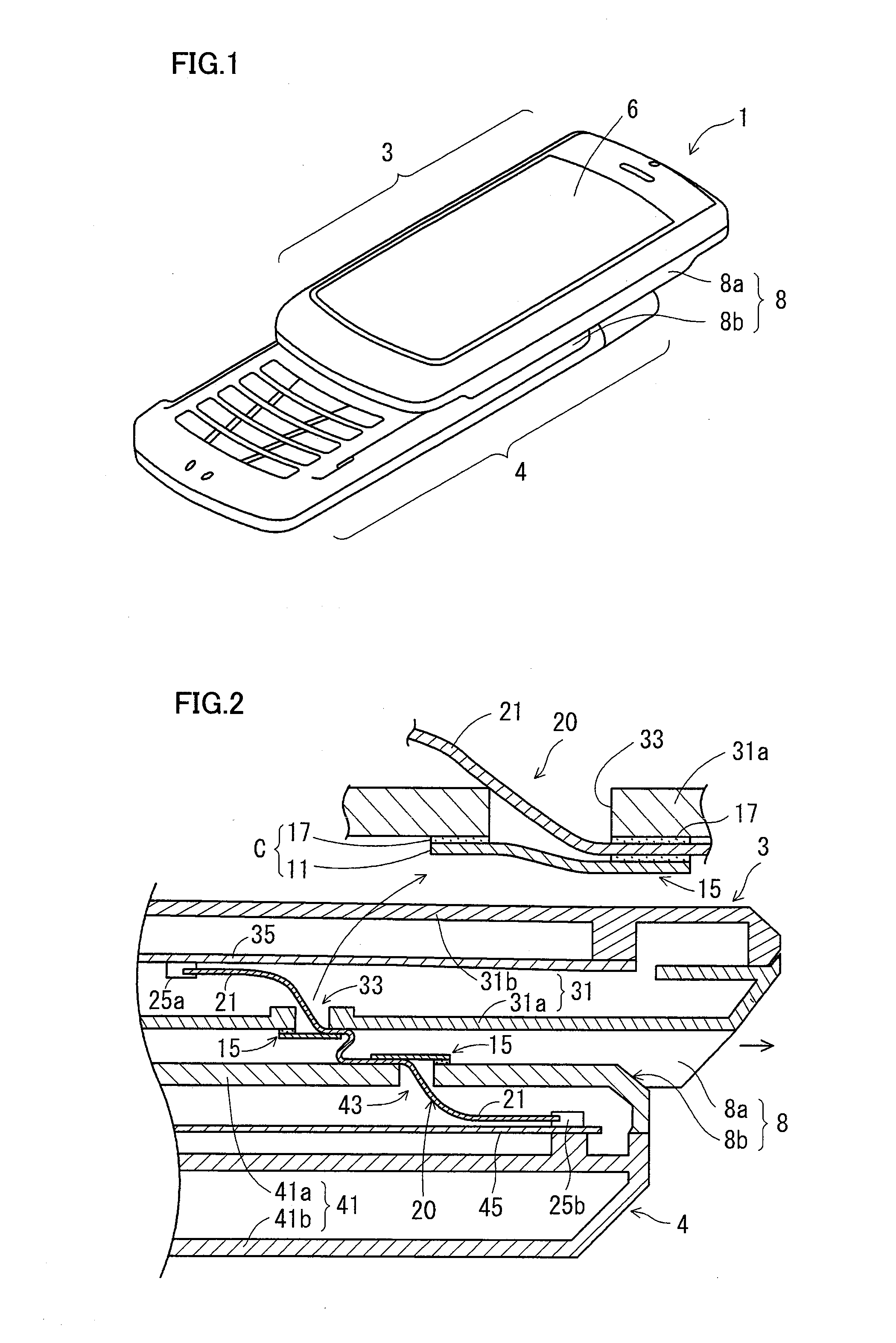
[0047]FIG. 1 is a perspective view schematically showing a structure of a portable terminal (electronic apparatus) to which the present invention is applied.

[0048]Portable terminal 1 includes a display unit 3 for displaying various kinds of information, an input unit 4 and a slide portion 8. Display unit 3 is provided with a display apparatus 6 for which a liquid crystal display panel is used, and a speaker, for example. Input unit 4 is provided with input keys and a microphone, for example. Slide portion 8 is configured to include an outer frame 8a provided on display unit 3 side and an inner frame 8b provided on input unit 4 side in such a manner that the frames are slidably fit with each other.

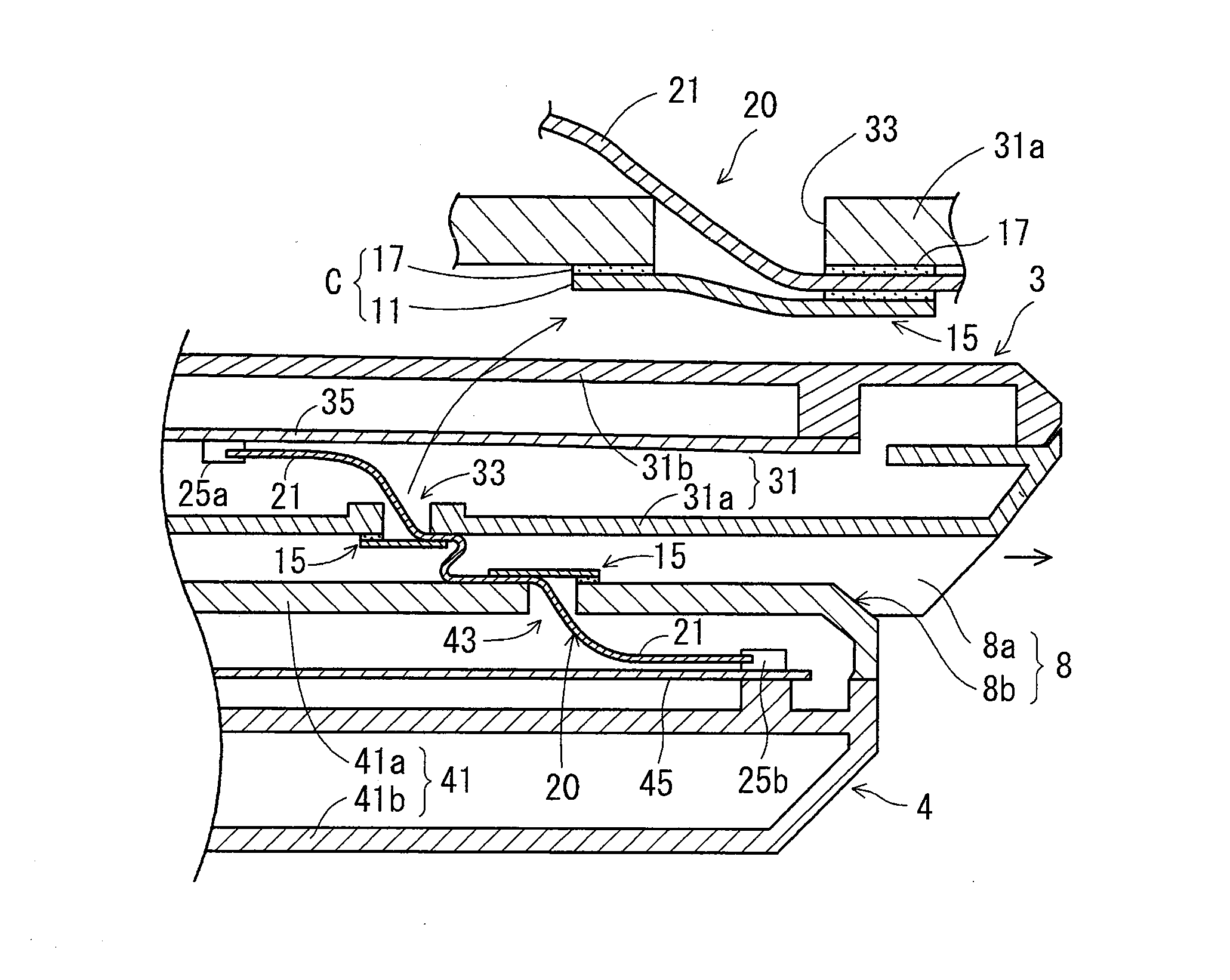
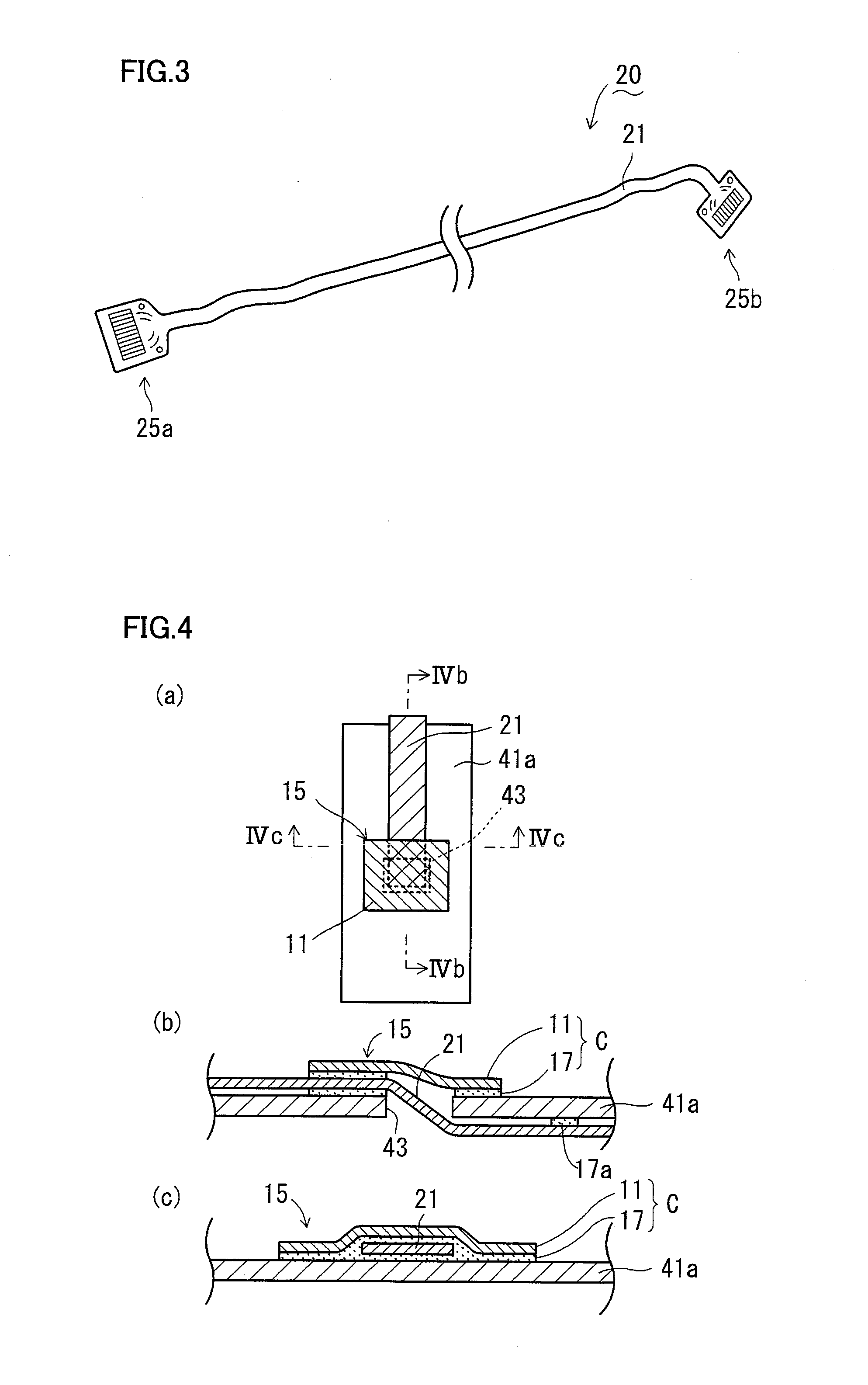
[0049]FIG. 2 is a cross section showing a structure of a connecting portion by means of slide portion 8 of portable terminal 1 according to a first embodiment. FIG. 3 is a plan view of a wire body 20.

[0050]Display unit 3 includes a display unit housing 31 and a display unit substrate 35 as ...

second embodiment

[0087]FIG. 8 (a) is a plan view showing in detail a structure around through hole 43 of input unit housing 41 in a second embodiment, FIG. 8 (b) is a cross section along line VIIIb-VIIIb and FIG. 8 (c) is a cross section along line VIIIc-VllIc. In the drawings, the same component as the first embodiment is denoted by the same reference character, and the description thereof will not be repeated. In connection with the present embodiment as well, a seal structure provided to slide portion 8 of the slide-type portable terminal as shown in FIG. 1 will be described.

[0088]In the present embodiment, in addition to the components in the first embodiment, a seal tape 19 sealing and attaching spacer member 11 to housing 41a is provided.

[0089]The structure around through hole 33 of display unit housing 31 is basically similar to the structure shown in FIG. 8 (a) to FIG. 8 (c).

[0090]In the present embodiment, seal tape 19 is provided in addition to the seal structure of the first embodiment. T...

first modification

of Third Embodiment

[0111]FIG. 12 is a cross section of a seal structure 15 according to a first modification of the third embodiment. In FIG. 12, the cross section of seal structure 15 as shown corresponds to the cross section of FIG. 11 (c).

[0112]Seal structure 15 of the present modification includes a seal tape 19 (tape member) that is laid over covering C and the peripheral region of the through hole of the housing, in addition to the components of the third embodiment.

[0113]As seal tape 19, so-called single-sided waterproof tape for example may be used. Seal tape 19 may be formed for example by applying butyl rubber, acrylic pressure-sensitive adhesive or the like to one side of a base film such as polyethylene “warifu” (split-fiber nonwoven fabric) base, polyester nonwoven fabric, aluminum foil or the like.

[0114]The present modification not only enhances the waterproof capability but also improves the reliability of seal structure 15. More specifically, when tensile stress or t...


PUM

PropertyMeasurementUnit
thicknessaaaaaaaaaa
thicknessaaaaaaaaaa
thicknessaaaaaaaaaa

Abstract

A seal structure capable of achieving a waterproof structure at low cost while being flexibly adaptable to design change of a wire member, a method of forming the seal structure, a wire body and an electronic apparatus using them are provided. A seal structure 15 for sealing through holes 33, 43 of housings 31, 41 in which a wire member 20 is inserted is configured to include a covering C that includes a spacer member 11 disposed on one side of the through hole, secures the spacer member 11, the wire member 20 and the housings 31, 41 to each other and seals them.

Description

TECHNICAL FIELD[0001]The present invention relates to a seal structure for a housing of a portable terminal, PDA, personal computer or the like, a method of forming the seal structure, a wire body, and an electronic apparatus including the seal structure and the wire body.BACKGROUND ART[0002]An FPC (Flexible Printed Circuit)-integrated gasket has been known. The FPC-integrated gasket has a seal structure for sealing a through hole provided in a housing of an electronic apparatus such as portable terminal.[0003]Patent Document 1 discloses in FIGS. 1 to 3 an FPC-integrated gasket integrated with an FPC (30) and formed in the shape of a grommet. The FPC-integrated gasket (1) includes a pair of gaskets (10) formed of a rubber-like elastic body. At an end of each gasket (10), a protrusion (50) for sealing a through hole (3) of a housing (2) is provided. The protrusion (50) has a tapered surface (53) tapering toward an end face (54) from a face (52) with a cross sectional area larger in d...

Claims


Application Information

Patent Timeline
Patent Type & Authority Applications(United States)
IPC IPC(8): H02G3/18B32B37/12
CPCH02G3/088H04M1/0237H05K5/0086H05K5/0247H05K7/1451H04M1/02H05K7/00
Inventor KASUGA, TAKASHIMISHIMA, HIDEHIKOMARUYAMA, KAZUYA
Owner SUMITOMO ELECTRIC IND LTD
Why Eureka
Try Eureka