
Image projection apparatus and method of controlling the same

a technology of image projection and apparatus, applied in the direction of color signal processing circuit, color television details, television system, etc., can solve the problems of complex computation, not desirable from the standpoint of product cost, and the need for complicated computation

Inactive Publication Date: 2011-01-06
CANON KK
View PDF20 Cites 27 Cited by
  • Summary
  • Abstract
  • Description
  • Claims
  • Application Information

AI Technical Summary

Benefits of technology

[0009]It is a feature of the present invention to provide an image projection apparatus and a method of controlling the same which can accurately and quickly generate color correction information for use to correct for the influence of ambient environment light even when a projection plane is colored.

Problems solved by technology

Such equipment, if used, will allow the illuminating light to be measured accurately, but is not desirable from the viewpoint of product costs.
However, complicated computations are required in order to generate a 3D-LUT which realizes both color correction on the projection plane and correction for the influence of ambient environment light at the same time.
This makes it necessary to carry out complicated computations again.

Method used


Image

  • Image projection apparatus and method of controlling the same
  • Image projection apparatus and method of controlling the same
  • Image projection apparatus and method of controlling the same

Examples


first embodiment

[0040]FIG. 3 is a block diagram describing a configuration of the color correction circuit 104 according to a

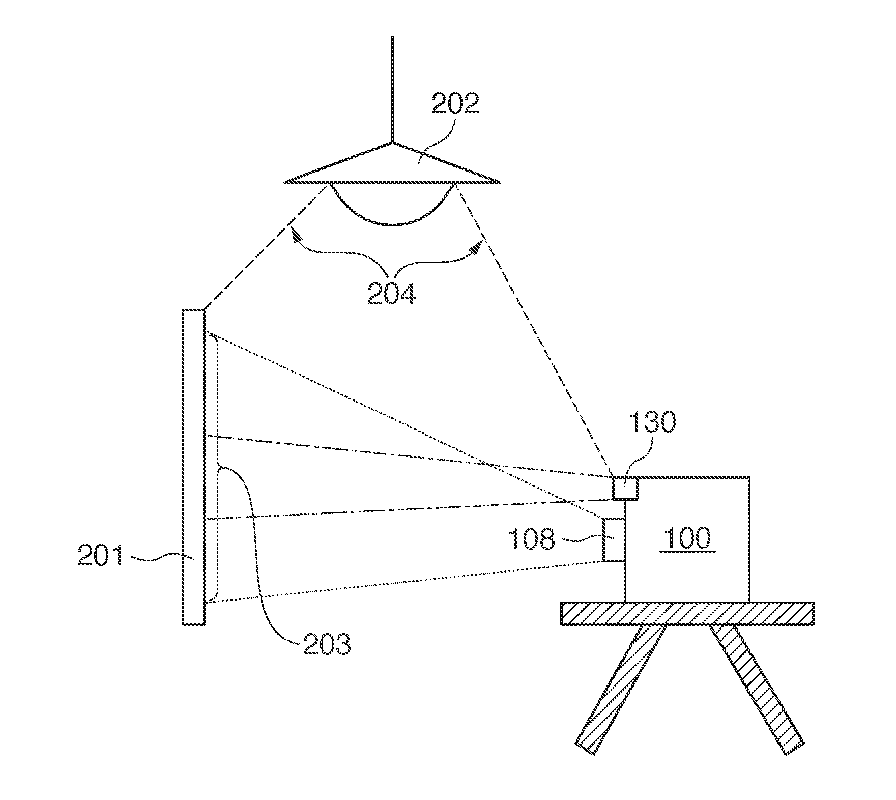
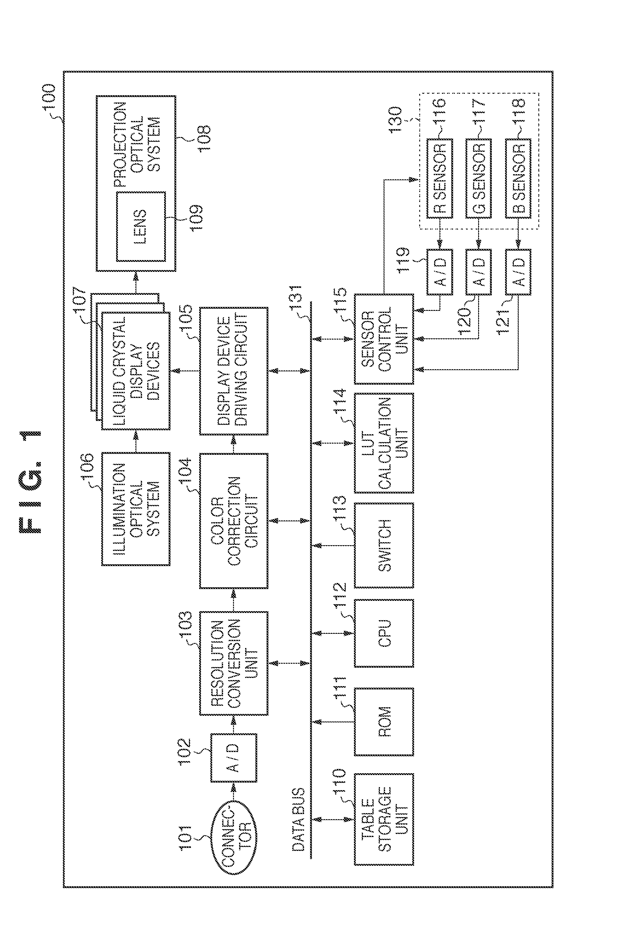
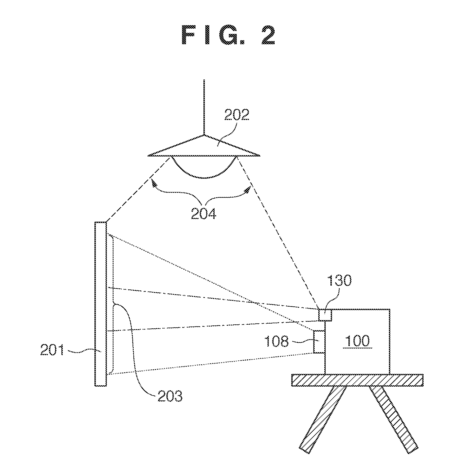
[0041]Output of the resolution conversion unit 103 is inputted in a selector 302. Output of a pattern generation circuit 301 which generates a calibration pattern for use to sense the color of the projection plane is also inputted in the selector 302. On instructions from the CPU 112, the selector 302 selects the output of the pattern generation circuit 301 when outputting a calibration pattern for use to sense the color of the screen 201. On the other hand, when a normal image is projected, the selector 302 selects the output of the resolution conversion unit 103. A coefficients storage unit 307 stores red gain (Ar), green gain (Ag), and blue gain (Ab) determined by undermentioned operations and received from the CPU 112. A multiplier 303 multiplies output of the selector 302 by output of the coefficients storage unit 307 and thereby adjusts the gains. Incidentally, although...

second embodiment

[0065]FIG. 7 is a block diagram describing a configuration of a color correction circuit 104 according to the

[0066]Output of the resolution conversion unit 103 is inputted in the selector 302. Output of a pattern generation circuit 301 which generates a calibration pattern for use to sense the projection plane is also inputted in the selector 302. On instructions from the CPU 112, the selector 302 selects the output of the pattern generation circuit 301 when a calibration pattern for color measurement of the screen 201 is used, and selects the output of the resolution conversion unit 103 when a normal image is projected. Output of the selector 302 is sent to a selector 310 and an address generation circuit 308. The address generation circuit 308 converts an output signal of the selector 302 into an address in the table storage unit 110 and sends the address to the table storage unit 110 via the data bus 131. The table storage unit 110 reads data out of the inputted address and sends...


PUM


Abstract

An image projection apparatus that can perform a wall color correction and an ambient light correction obtains a wall color correction parameter by projecting a calibration image for the wall color correction and then obtains an ambient light correction parameter by projecting a calibration image for the ambient light correction, which has been subjected to the wall color correction using the wall color correction parameter.

Description

BACKGROUND OF THE INVENTION[0001]1. Field of the Invention[0002]The present invention relates to an image projection apparatus and a method of controlling the same.[0003]2. Description of the Related Art[0004]Recently, liquid crystal projectors that can simply and easily display a large screen by projection have come to be used widely in making presentations in meetings or displaying movie content at home. The liquid crystal projectors are used in various lighting environments, and it is desirable to carry out color reproduction according to actual lighting in projection environments. On the other hand, CIECAM02 (CAM: Color Appearance Model), which is a chromatic adaptation model, published by CIE and other models have been developed for color matching technology. Using these techniques and taking into consideration the lighting environments and the like of liquid crystal projectors, color reproduction is becoming a possibility.[0005]To apply color reproduction to a liquid crystal p...

Claims


Application Information

Patent Timeline
IPC IPC(8): H04N9/31H04N9/64
CPCH04N9/3182H04N9/3191H04N17/045H04N9/3197H04N9/73H04N9/3194
Inventor KAWAHARA, NORIHIRO
Owner CANON KK
Learn More