Magnified-projection optical system and digital type planetarium device

Active Publication Date: 2011-01-06
KONICA MINOLTA OPTO
View PDF9 Cites 24 Cited by
  • Summary
  • Abstract
  • Description
  • Claims
  • Application Information

AI Technical Summary

Benefits of technology

[0052]The present invention provides a high-performance magnified-projection optical system charac

Problems solved by technology

In recent years, to increase the brightness of the image projected on the screen, there has been a growing tendency to increase the size of the illuminatio

Method used


Image

  • Magnified-projection optical system and digital type planetarium device
  • Magnified-projection optical system and digital type planetarium device
  • Magnified-projection optical system and digital type planetarium device

Examples


example

Example 1

[0198]The following describes the first Example of the magnified-projection optical system of the present invention: The structure of the first Example is the same as those of FIGS. 2 through 4.

[0199]The following shows the construction data of each lens in the first Example:

Numerical value of Example 1Unit: mmSurface dataSurface number:rdndvdScreen: 6250.0006250.001116.3366.001.5168064.20243.90213.953110.0393.341.6204160.34426.32214.455363.0382.601.6584450.85623.89114.507−26.7992.301.7440044.908−82.79212.059−52.6112.231.8051825.4610457.0991.6011554.59410.801.6034238.0112−35.4170.20132085.7846.151.6034238.0114−69.0000.201550.0307.601.5168064.2016−498.56031.301713.4442.301.7552027.531810.31110.4019(stop)∞1.8020−141.6341.861.7440044.902116.0112.831.5168064.2022−31.4258.022328.1645.001.4970081.6124−25.0920.2525−194.5582.401.8061040.732620.7032.602738.2074.901.4970081.6128−32.5630.402939.1165.501.4970081.6130−43.05319.2531(dummy)91.513290.37110.501.4970081.6133−77.9483.503476.2...

example 2

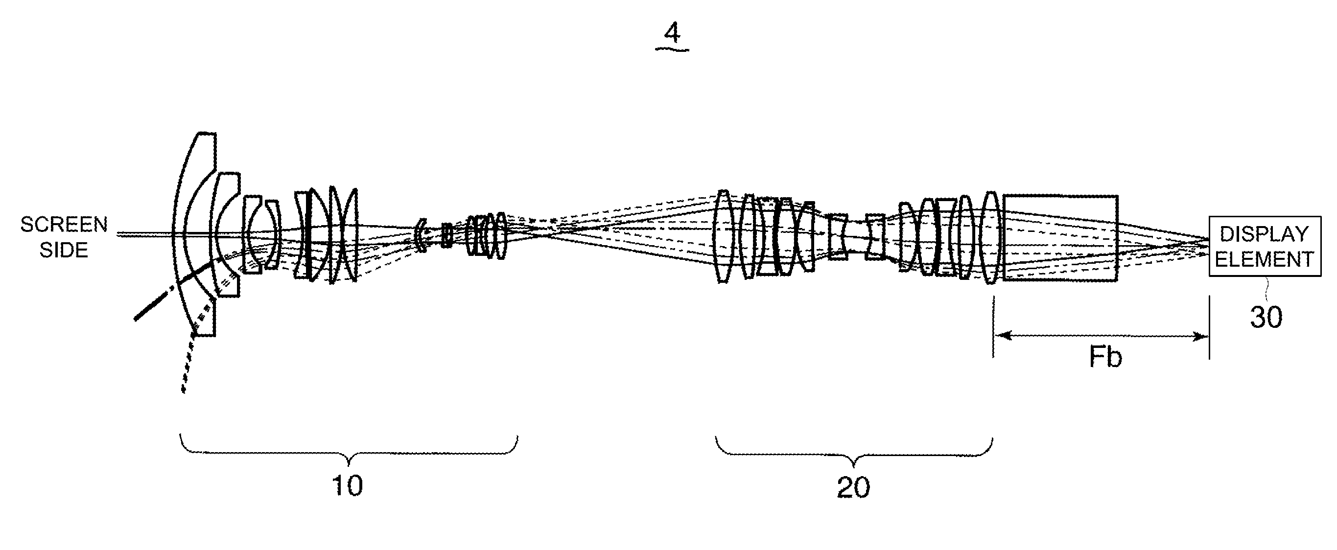
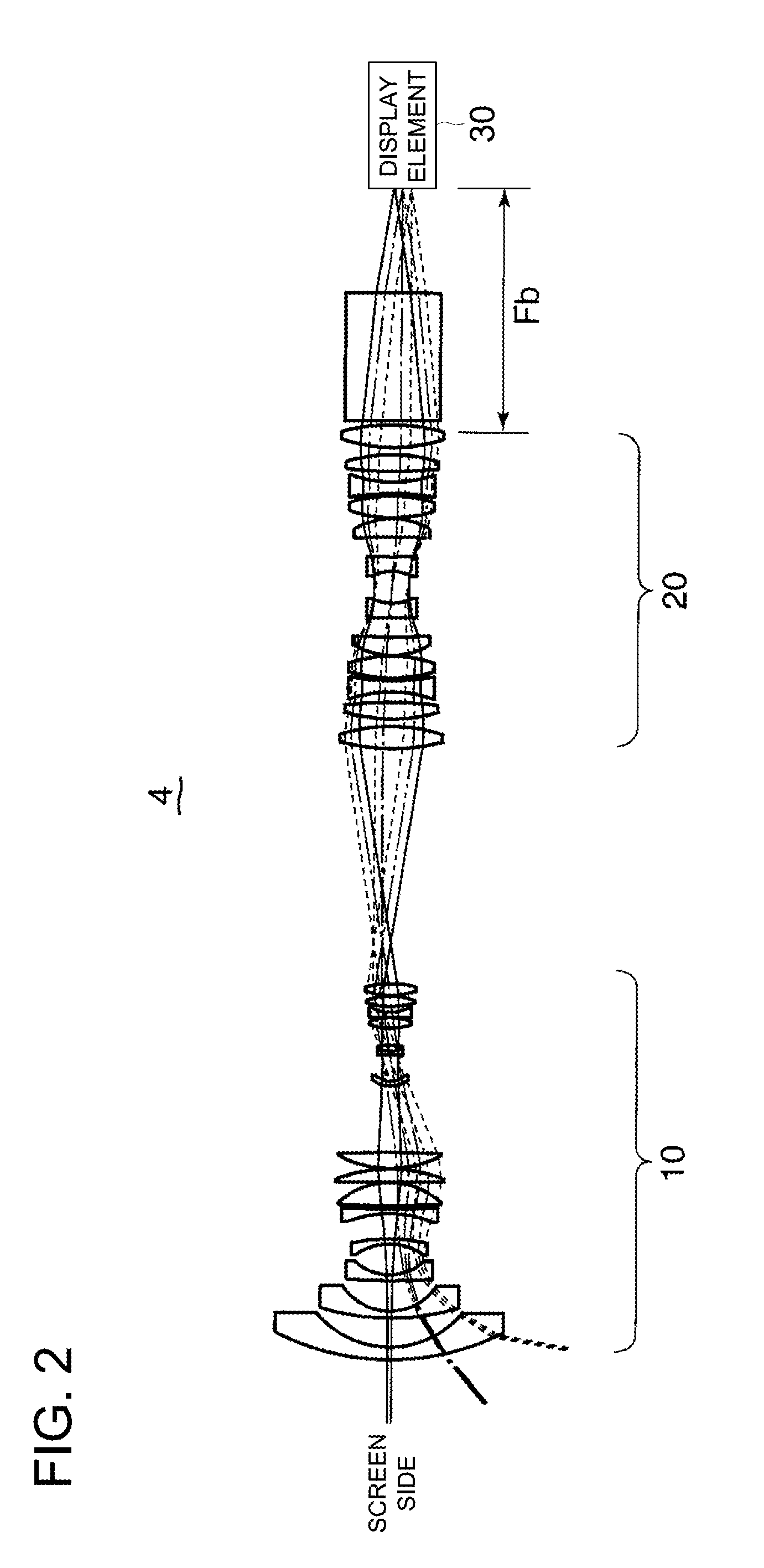
[0202]The following describes the magnified-projection optical system of the second Example. FIG. 7 overall schematic diagram representing the magnified-projection optical system. As shown in FIG. 7, the magnified-projection optical system 4 of the second Example includes a projection optical system 10, relay optical system 20 and display element 30 sequentially arranged along the optical axis K1 in that order as viewed from the screen 1, similarly to the case of FIG. 2.

[0203]FIG. 8 is the overall schematic diagram representing the projection optical system 10. FIG. 9 is the overall schematic diagram representing the relay optical system 20 in the second Example. As will be apparent from comparison with FIG. 4, in the relay optical system 20 of FIG. 9, the length of the prism PR1 in the direction of optical axis K1 is greater than that of FIG. 4.

[0204]The following describes the construction data of each lens in the second Example.

Numerical value of Example 2Unit: mmSurface dataSurf...


PUM


Abstract

Provided is a magnified-projection optical system, which can retain a considerably long back focus although a focal length is short and which has a small chromatic aberration. The optical system comprises a projecting optical system, a relay optical system and a display element, which are sequentially arrayed from a screen side along the optical axis. The projecting optical system enlarges and projects the image, which has been linearly focused by the relay optical system, on the screen, and includes a negative group and a positive group arrayed sequentially from the screen side and having a negative optical power and a positive optical power, respectively. The optical system satisfies the following conditional relations of |Fb/F|>10 and 0.5<|F/Fp|<2.0, wherein Fb: the back focus of the whole optical system including the projecting optical system and the relay optical system, F: the focal length of the whole optical system, and FP: the focal length of the projecting optical system,

Description

FIELD OF THE INVENTION[0001]The present invention relates to a projection optical system for projecting an image outputted from the display element such as a liquid crystal element and digital device.BACKGROUND OF THE INVENTION[0002]In amusement facilities and others, a digital image is projected on a large-sized screen and dome-type screen in recent years: One of the known display devices for implementing this operation is a display device using a display element such as a liquid crystal element and digital micro-device, instead of the display device for projecting a film on a screen. This type of display device is equipped with a display element for outputting each of the R, G and B, for example, a prism for color-superimposition of the image outputted from each display element, a projection optical system for enlarging and projecting an image color-superimposed by the prism, and a screen for displaying the enlarged and projected image.[0003]The display element to be adopted in th...

Claims


Application Information

Patent Timeline
IPC IPC(8): G02B27/18
CPCG02B13/06G03B21/14G02B13/22G09B27/00
Inventor SHIMO, MITSUAKITAKAMOTO, KATSUHIRO
Owner KONICA MINOLTA OPTO
Why Eureka
Try Eureka