Radio frequency power amplifier

a power amplifier and radio frequency technology, applied in the direction of antennas, electrical equipment, electrical long antennas, etc., can solve the problems of insufficient suppression and decrease in the efficiency of the power amplifier, and achieve the effect of high isolation and high efficiency

Inactive Publication Date: 2011-01-06
PANASONIC CORP
View PDF6 Cites 22 Cited by
  • Summary
  • Abstract
  • Description
  • Claims
  • Application Information

AI Technical Summary

Benefits of technology

[0014]The object of the present invention is to solve these problems and to provide an RF power amplifier which ensures high isolation between output terminals and achieves high efficiency.
[0030]According to the present invention, it is possible to provide an RF power amplifier which secures high isolation between output terminals and achieves high efficiency.FURTHER INFORMATION ABOUT TECHNICAL BACKGROUND TO THIS APPLICATION

Problems solved by technology

However, the conventional configuration shown in FIG. 10 has a problem of insufficient suppression of a power leakage into the second output port due to a parasitic inductance component of the second switch element when operating at the first frequency signal.
This causes a problem of decreasing efficiency of the power amplifier.

Method used


Image

  • Radio frequency power amplifier
  • Radio frequency power amplifier
  • Radio frequency power amplifier

Examples


first embodiment

Variation of First Embodiment

[0095]FIG. 3 is a diagram showing a schematic view of a circuit configuration when extended to be multiband and multimode.

[0096]Compared to the RF power amplifier A shown in FIG. 1, for the RF power amplifier A′ shown in the figure, each of the first and the second frequency ranges includes plural bands. Accordingly, the RF power amplifier A′ includes: amplifier output terminals A1 to Am (m is an integer equal to or larger than 2) corresponding to respective bands of the first frequency range; amplifier output terminals B1 to Bn (n is an integer equal to or larger than 2) corresponding to respective bands of the second frequency range; matching circuits MA1 to MAm corresponding to the respective bands of the first frequency range; and matching circuits MB1 to MBn corresponding to the respective bands of the second frequency range. In addition, the RF power amplifier A′ includes, in place of the first switch 109, a first switch 121 having a switch output ...

second embodiment

[0107]An RF power amplifier according to a second embodiment differs from the RF power amplifier A according to the first embodiment in that the RF power amplifier according to the second embodiment further includes a capacitor having one end electrically connected to a second RF transmission line and the other end grounded. This allows the RF power amplifier according to the present embodiment to be more compact and more efficient than the RF power amplifier A according to the first embodiment. The following description will be focused on the difference from the first embodiment.

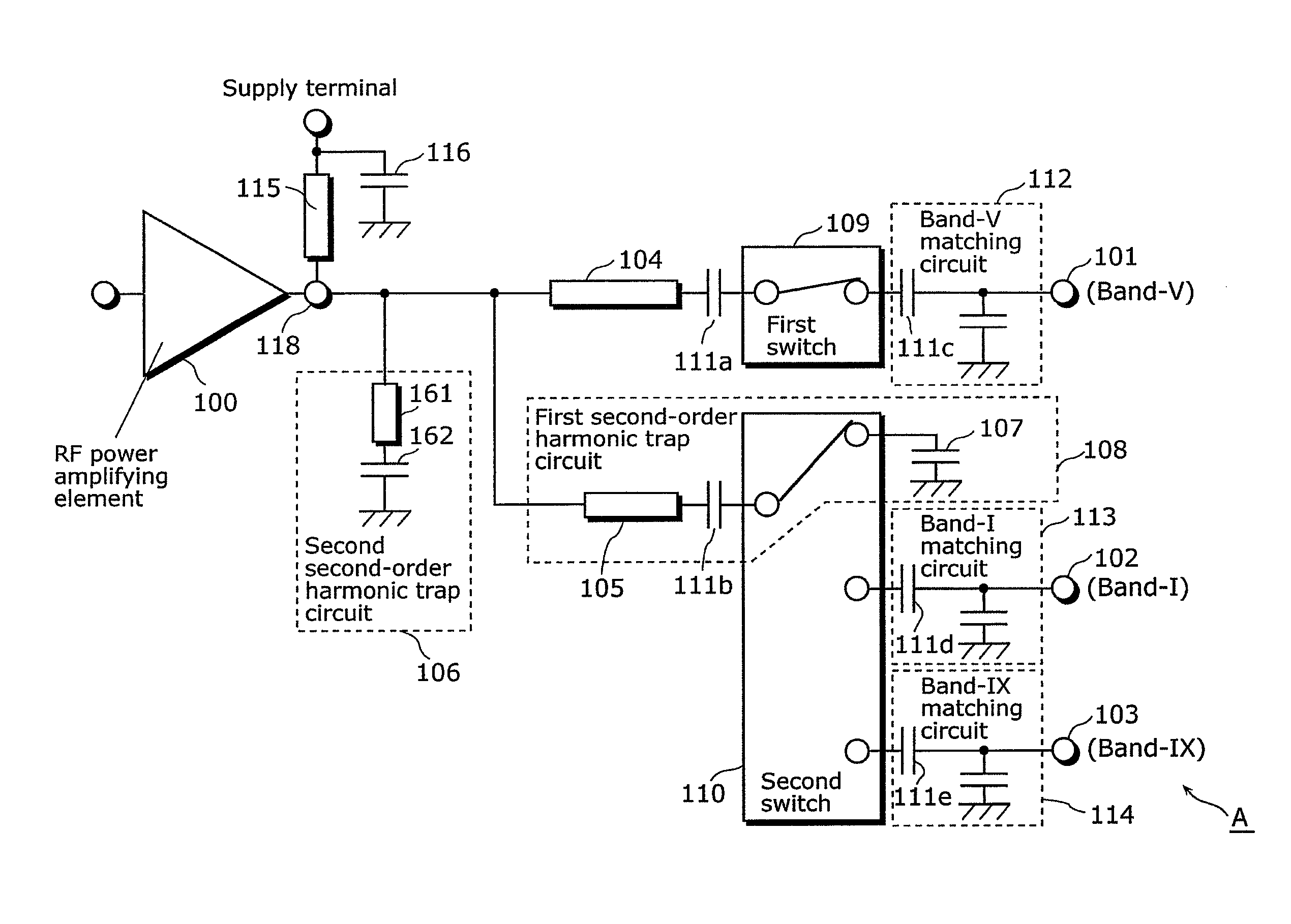
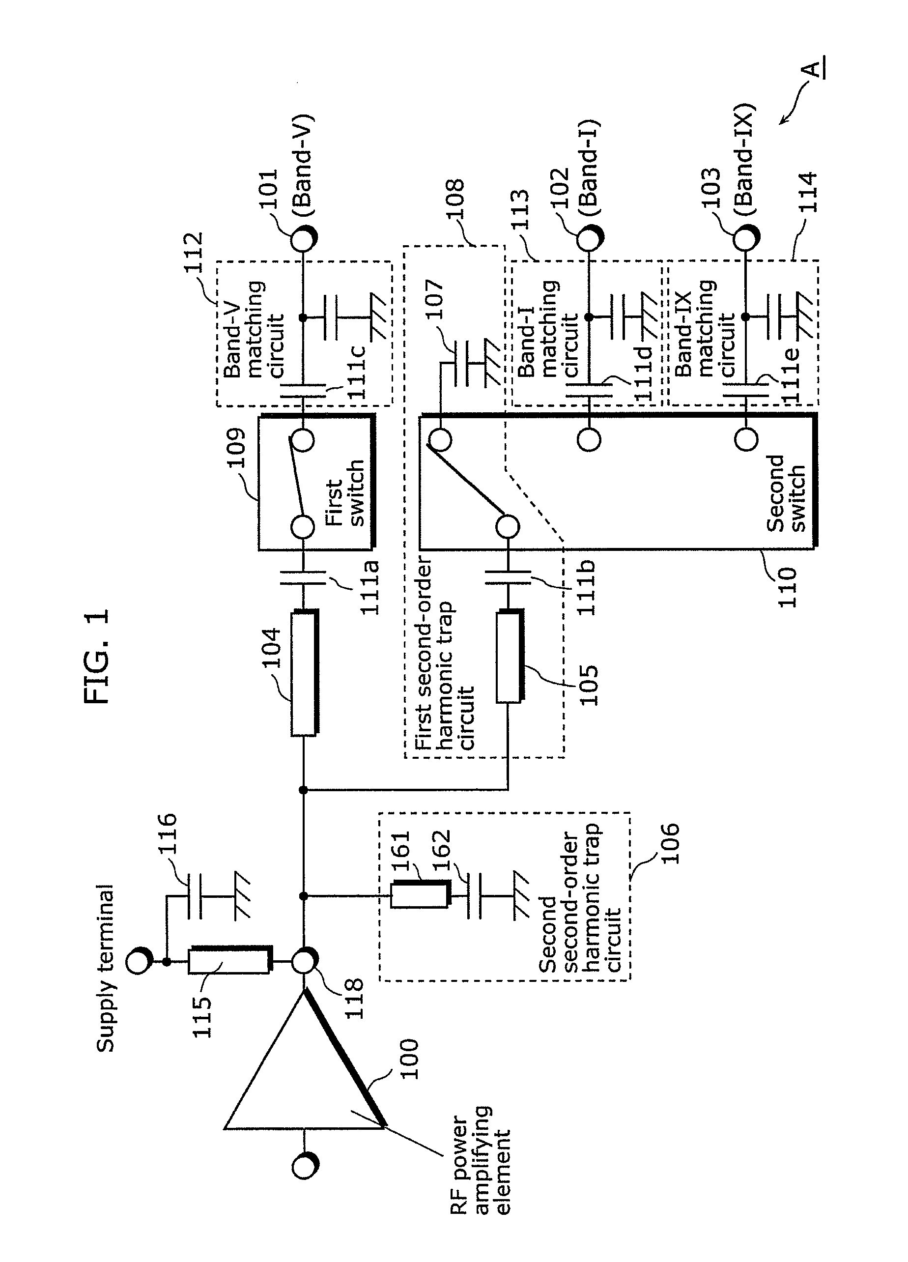
[0108]FIG. 4 is a diagram showing a schematic view of a circuit configuration of an RF power amplifier according to the second embodiment. Compared to the RF power amplifier A shown in FIG. 1, the RF power amplifier B shown in FIG. 4 includes a grounded capacitor 201 having one end connected to the transmission line 105 via the DC-cutting capacitor 111b and the other end grounded. In addition, the first sec...


PUM


Abstract

An RF power amplifier according to the present invention includes: an RF power amplifying element, a first switch provided in a first transmission path for transmitting a first RF signal output from the RF power amplifying element, a second transmission unit which transmits a second RF signal of higher frequency than the first RF signal output from the RF power amplifying element, and a second second-order harmonic trap circuit connected to an output terminal, and the second transmission unit includes a grounded capacitor, a second transmission path, a Band-I matching circuit, a second switch connected in series to the second transmission path, and the second switch connects the second transmission path to the grounded capacitor when the first RF signal is amplified, and connects the second transmission path to the Band-I matching circuit when the second RF signal is amplified.

Description

BACKGROUND OF THE INVENTION[0001](1) Field of the Invention[0002]The present invention relates to a radio frequency (RF) power amplifier used for a mobile communication device and so on.[0003](2) Description of the Related Art[0004]With recent development in mobile communication systems, there is a growing demand for compatibility with multiple bands and multiple modes in accordance with different mobile communication systems which specify different usable frequency ranges and modulation methods.[0005]Conventionally, in response to the demand for such compatibility with multiple bands and multiple modes, a method conventionally used for the RF power amplifier used in a sending portion of the mobile communication device is to arrange an RF power amplifier corresponding to each frequency band and modulation system to be used, or to provide a module in which plural RF power amplifying elements and a matching circuit are integrated as a package.[0006]However, in these methods, a larger ...

Claims


Application Information

Patent Timeline
Patent Type & Authority Applications(United States)
IPC IPC(8): H01Q11/12
CPCH01Q23/00
Inventor MAKIHARA, HIROKAZUTATEOKA, KAZUKIINAMORI, MASAHIKOMATSUDA, SHINGO
Owner PANASONIC CORP
Why Eureka
Try Eureka