
Head for the automatic positioning of fibre blankets

a technology of automatic positioning and fibre blankets, which is applied in the directions of paper hanging, transportation and packaging, packaging, etc., can solve the problems of inability to ensure the uniformity of the design features of the parts which are manufactured, and the lack of sufficient means for prefabricated structures to make quality parts, etc., and achieves the effect of greater simplicity and quick manufacturing

Inactive Publication Date: 2011-01-13
IDEKO SCOOP
View PDF5 Cites 6 Cited by
  • Summary
  • Abstract
  • Description
  • Claims
  • Application Information

AI Technical Summary

Benefits of technology

[0005]According to the present invention, a head for the automatic positioning of fibre blankets on large surfaces is described, this head being able to be used for the manufacture of both large structural parts and of parts of any other type, although it is in the former in which the head provides greater advantages in its use. This automatic positioning is truly advantageous compared to conventional manual solutions, both due to the greater simplicity and quickness in the manufacture and due to the quality of the finishes and the uniformity of the parts thus obtained.
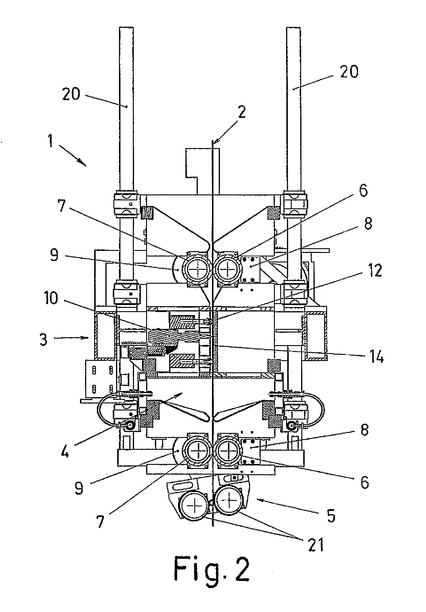
[0006]The head object of the present invention has three differentiated zones; a cutting zone, an impregnation zone and a positioning zone for the fibre blankets. The head automatically applies said fibre blankets on the corresponding moulds or mandrels, assuring the quality and the uniformity of the parts obtained. Furthermore, this is achieved with a repetitive process which is much quicker and simpler than the manual processes known up until now.
[0010]Once the fibre blanket has been impregnated, it passes via the lower set of rollers until reaching the positioning zone, which consists of at least one pressure roller. According to a possible practical embodiment, it has been envisaged that there are two pressure rollers assembled in a rocker; such that, depending on the position occupied by this rocker, one or the other of these two rollers acts. Thus, when the head moves in the advance direction, one of the rollers acts and, upon moving backwards, the other one acts, allowing the positioning of the fibre blanket both in the advance and in the retreat of the head. The change from one roller to the other takes place automatically, without needing an intervention of the operator.
[0012]With this head object of the invention, parts can therefore be formed automatically from fibre blankets, allowing making use of the lightweight and strength features of said material. Furthermore, structural parts with large dimensions can be manufactured by means of this head, thus obtaining the advantages in terms of transport and handling offered by the structural parts thus formed.

Problems solved by technology

However, the use of materials of this type in the construction of prefabricated structures lacks sufficient means for making quality parts, the application processes being basically manual, so uniformity in the design features of the parts which are manufactured cannot be assured in the results.

Method used


Image

  • Head for the automatic positioning of fibre blankets
  • Head for the automatic positioning of fibre blankets
  • Head for the automatic positioning of fibre blankets

Examples


Embodiment Construction

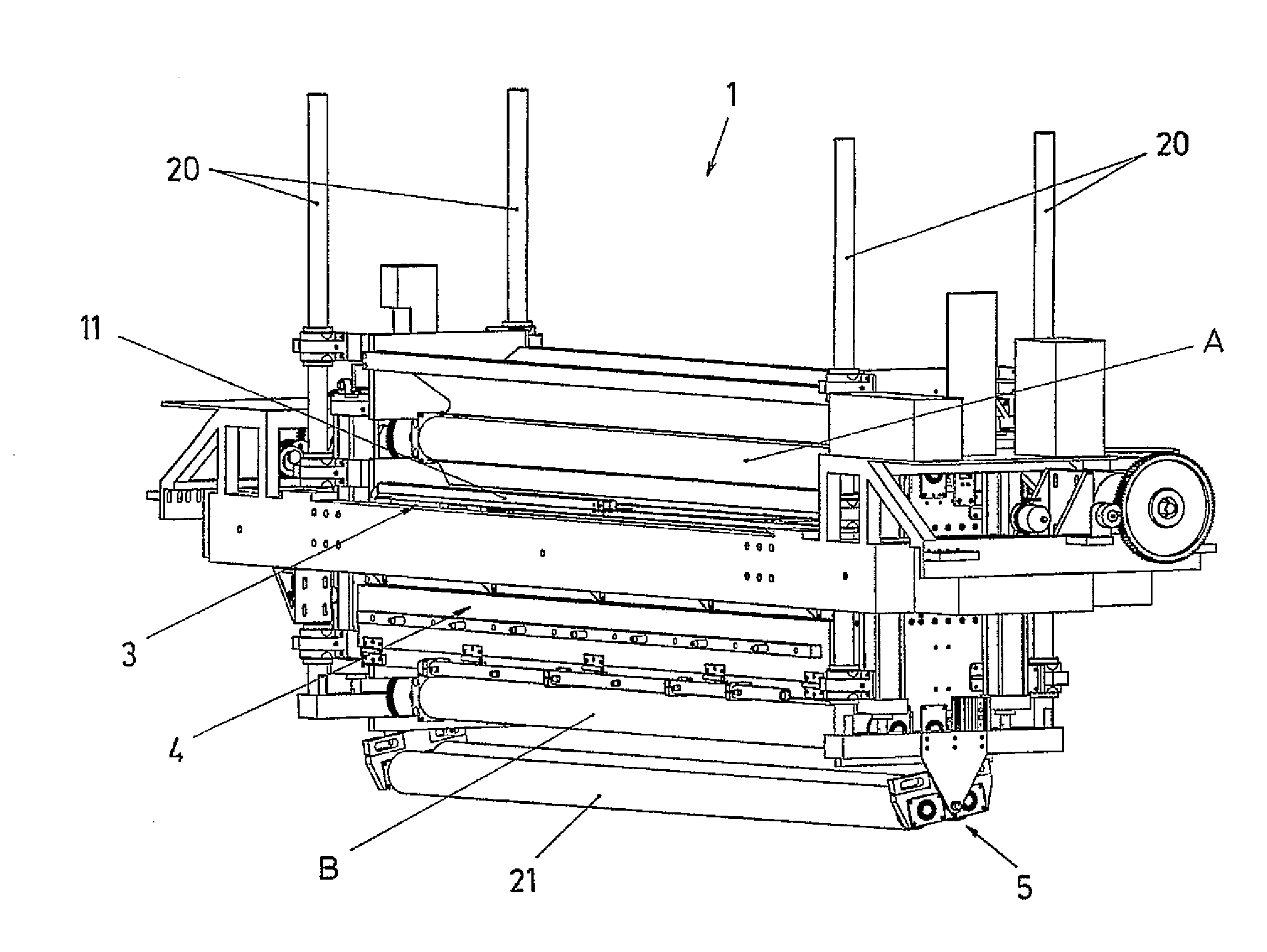
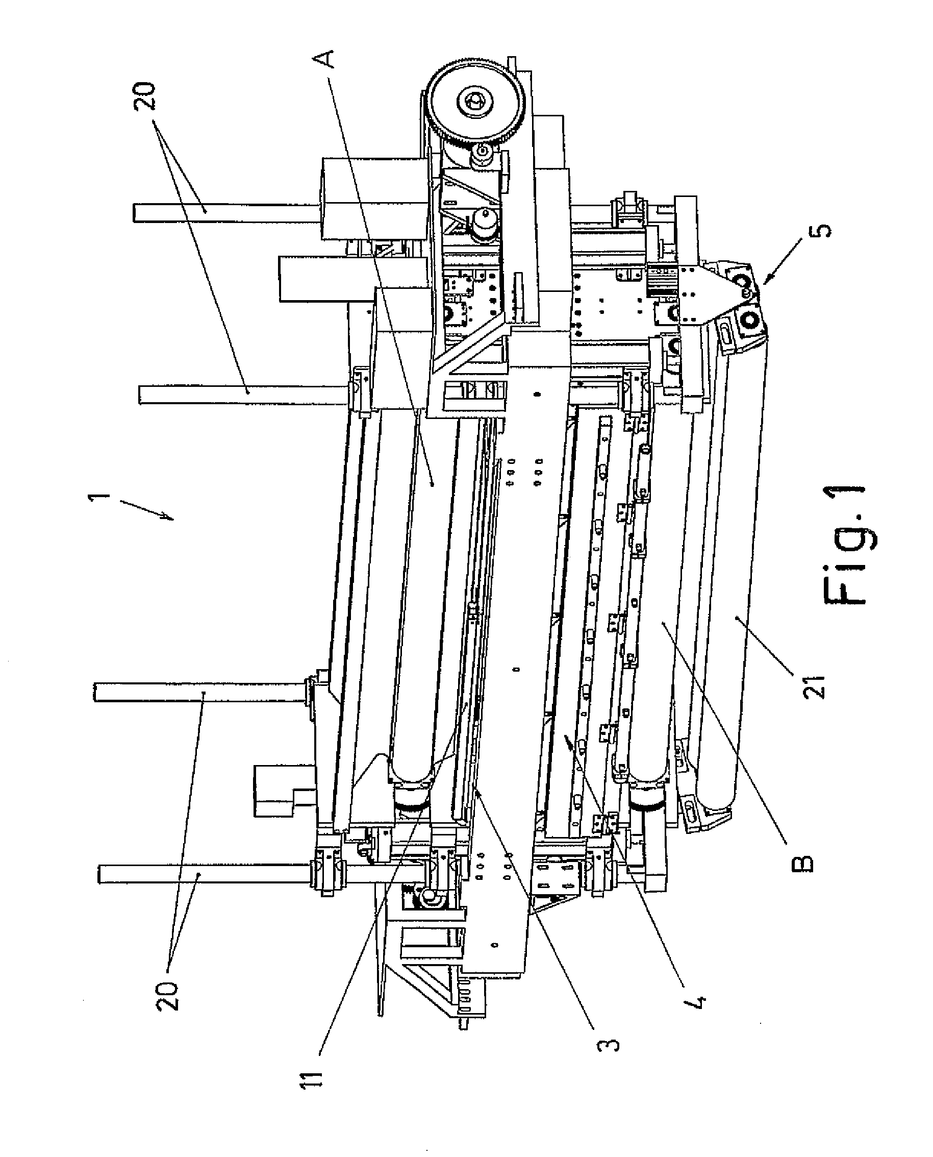
[0018]According to the present invention, a head (1) for the positioning of fibre blankets (2) in the manufacture of all types of parts, particularly in the manufacture of large structural parts, is proposed. The head (1) allows performing an automated process, gaining in quickness, precision, quality and homogeneity compared to conventional manual solutions.

[0019]The head (1) comprises an impregnation zone (4) in which the blanket (2) is impregnated with the resin necessary for the application thereof, a positioning zone (5) for positioning the fibre blankets on the surface of the mould or mandrel and a cutting zone (3) which allows cutting the blanket (2) at the ends of the extensions of the blanket (2) once positioned.

[0020]The head (1) furthermore incorporates individual sets of rollers (A and B) that convey and control the tension of the fibre blanket (2) at different points of the path from the feeding thereof in the head (1) to its exit towards the positioning zone on the cor...


PUM

PropertyMeasurementUnit
tensionaaaaaaaaaa
speedaaaaaaaaaa
pressureaaaaaaaaaa

Abstract

Head for the automatic positioning of fibre blankets, which determines a path for the fibre blanket (2) to be positioned, as far as a positioning zone (5), passing via a resin-impregnation zone (4) and via a cutting zone (3), including, in front of and behind said zones (3 and 4) individual sets of rollers (6-7) that convey the fibre blanket (2) and control the tension thereof.

Description

FIELD OF THE ART[0001]The present invention relates to the installations and processes which allow constructing all types of parts and preferably large structural parts by means of the application of successive fibre blankets, which are deposited one on top of the other until reaching the required thickness. The invention proposes a head for the automatic positioning of such fibre blankets, overcoming the drawbacks of conventional solutions which used basically manual processes.STATE OF THE ART[0002]In different fields, such as the construction field, large prefabricated structural parts are used, which are conventionally constructed from reinforced concrete, prestressed concrete, steel and / or the like, said parts thus having a weight which makes the transport and handling thereof complicated.[0003]Therefore, materials of another type have started to be used in the construction of these prefabricated structures, as is the case of fibre and resin composites, resulting in parts with a...

Claims


Application Information

Patent Timeline
Patent Type & Authority Applications(United States)
IPC IPC(8): B05B13/02B26D7/06
CPCB29C70/388B29C70/545Y10T156/1357Y10T156/1798Y10T156/179Y10T156/1383Y10T156/1361Y10T83/202B29C2793/0027
Inventor LIZARRALDE DORRONSORO, RAFAELZATARAIN GORDOA, MIGUEL MARIA
Owner IDEKO SCOOP
Learn More