

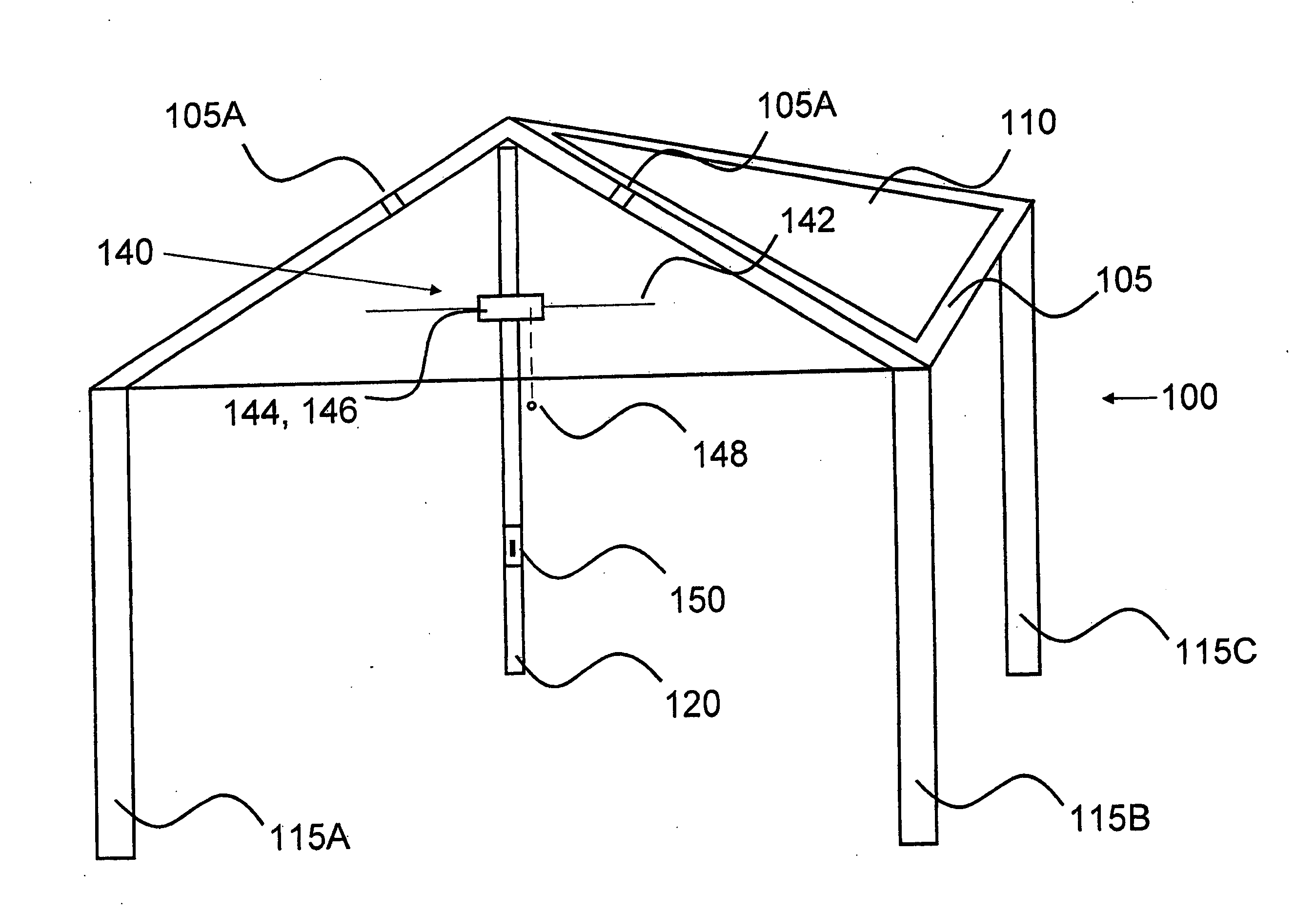
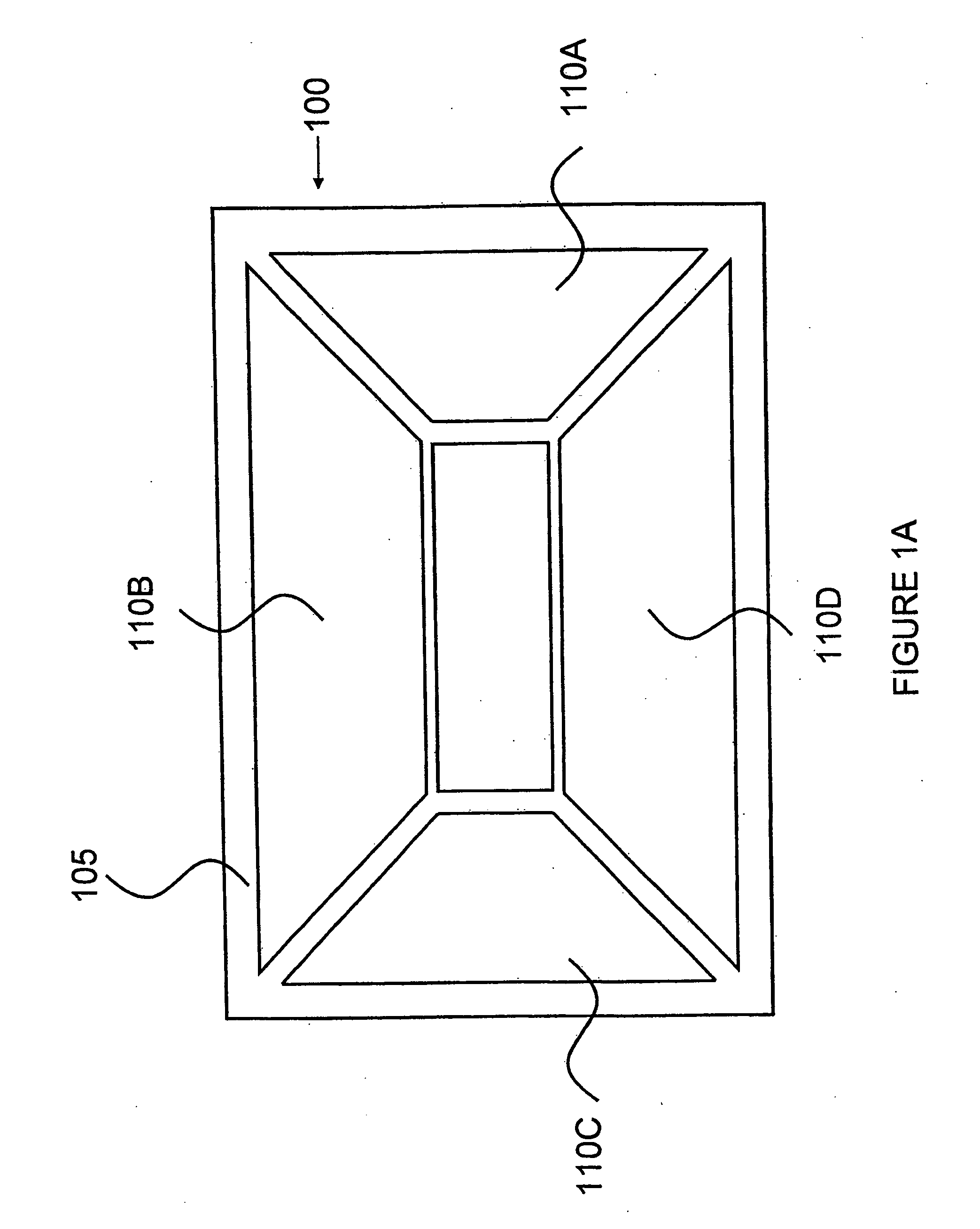
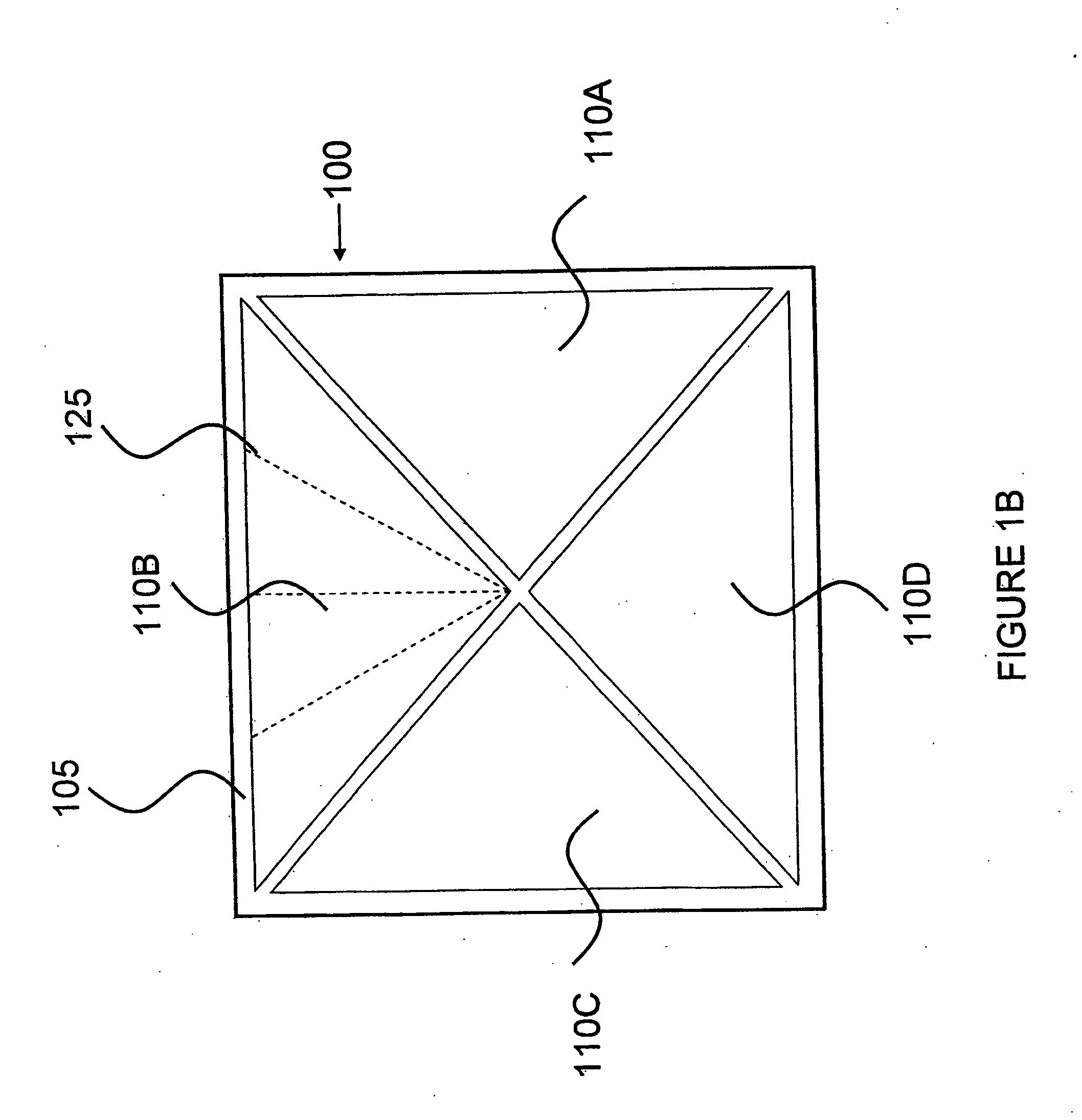
Portable solar canopy with modular connections
a solar canopy and modular technology, applied in the direction of machines/engines, heat collector mounting/support, light and heating apparatus, etc., can solve the problems of fan powering both permanent and non-modular, reference utterly fails to describe or suggest solar power source, fan cannot be substituted for another device using the same power source, etc., to achieve cost-effective sources of energy
- Summary
- Abstract
- Description
- Claims
- Application Information
AI Technical Summary
Benefits of technology
Problems solved by technology
Method used
Image

Examples
Embodiment Construction
The present invention will now be described more fully hereinafter with reference to the accompanying Drawings, in which preferred embodiments of the invention are shown. It is, of course, understood that this invention may, however, be embodied in many different forms and should not be construed as limited to the embodiments set forth herein; rather, these embodiments are provided so that the disclosure will be thorough and complete, and will fully convey the scope of the invention to those skilled in the art. It is, therefore, to be understood that other embodiments can be utilized and structural changes can be made without departing from the scope of the present invention.
As noted, humankind has long thought of adding a fan device to an umbrella or considered various ways to utilize personal fans. Up to now, however, these usages have not considered or suggested a portable solar canopy pursuant to the present invention, particularly in view of very recent technological advances w...
PUM
 Abstract
Description
Claims
Application Information