Deployment System

a deployment system and coiled tubing technology, applied in the direction of sealing/packing, drilling pipes, wellbore/well accessories, etc., can solve the problems of occupying valuable space, requiring substantial reels of coiled tubing, and being extremely difficult to accommodate, so as to reduce the time required

Inactive Publication Date: 2011-01-13
AX S TECH
View PDF18 Cites 16 Cited by
  • Summary
  • Abstract
  • Description
  • Claims
  • Application Information

AI Technical Summary

Benefits of technology

[0014]The spoolable tubular member may comprise a continuous length of tubing extending between the subsea assembly and the surface. This arrangement may therefore eliminate the requirement for multiple connections to be utilised. In alternative embodiments the spoolable tubular member may comprise two or more separate lengths adapted to be coupled together. This may permit the downhole deployment system to be readily installed and utilised in extreme water depths which may require a length of tubular beyond that which is conventionally provided in a single reel or spool. Furthermore, this arrangement may permit a length of tubing to be reused in deeper locations. The separate lengths of tubing may be coupled together by, for example, welding, threaded connections, quick-connect type connections and the like. The system may comprise a tubing connector adapted to couple separate lengths of tubing together. A connector as described in applicant's co-pending application of equal filing date may be provided.
[0085]The tubular member may be adapted to be coupled to a supporting assembly mounted on a surface vessel. The supporting assembly may comprise a lifting frame adapted to apply and maintain tension in the tubular member. This arrangement may prevent or minimise the risk of collapse or buckling of the tubular member.

Problems solved by technology

However, it is often the case that a store of tools are required to be held on site to be ready for use as appropriate, which accordingly takes up valuable space.
Furthermore, many offshore wells are located in water depths exceeding several thousand metres and as such deploying tools through a subsea wellhead and into a wellbore first have to be tripped through the water depth within a marine riser.
The depth of most conventional wellbores, however, requires a significant length of coiled tubing to be available which thus requires substantial reels of the coiled tubing which would be extremely difficult to accommodate entirely within a subsea intervention system.
However, the connections are time consuming to make-up, and the marine riser formed in this manner is normally relatively stiff, thus minimising the degree of permitted deviation of a surface vessel.
This in turn may require specialised vessels to be utilised, which may be difficult to obtain due to demand, and are expensive.

Method used


Image

  • Deployment System
  • Deployment System
  • Deployment System

Examples


Embodiment Construction

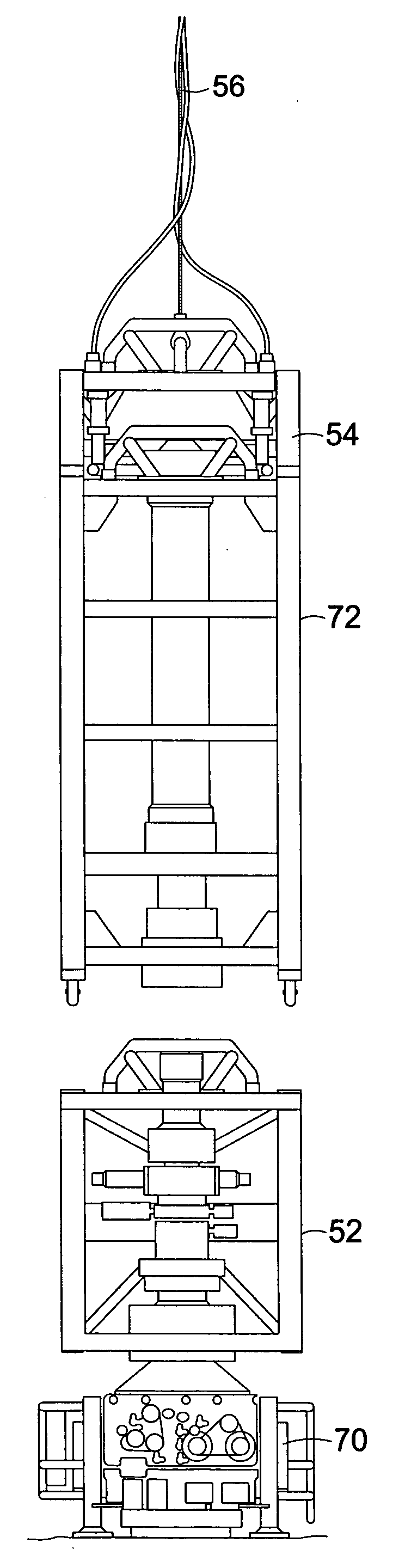
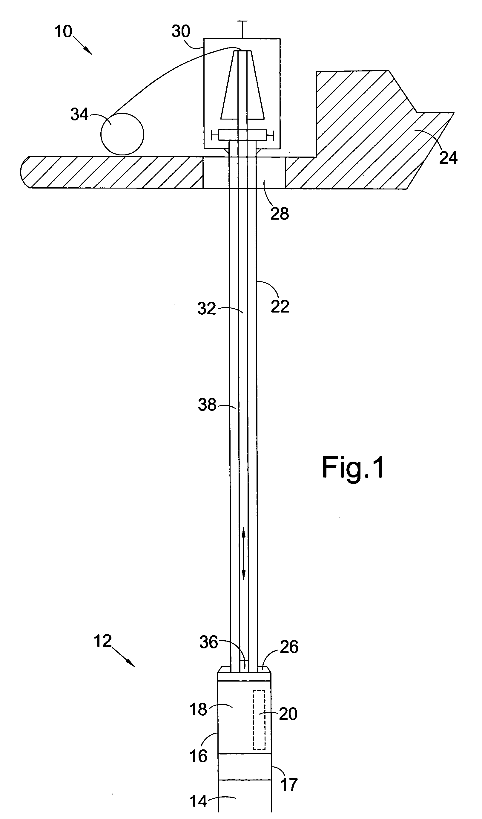
[0125]Referring to the FIG. 1, a tool deployment system according to an embodiment of an aspect of the present invention is shown diagrammatically. The tool deployment system, generally identified by reference numeral 10, includes a subsea assembly 12 mounted on an existing subsea wellhead 14. The subsea assembly 12 comprises a tool storage package 16 which defines a tool storage chamber 18 containing a plurality of downhole tools 20 (only one shown for clarity). The tool storage chamber 18 may contain intervention tools, drilling tools, logging tools or the like, or any suitable combination of tools selected from the art.

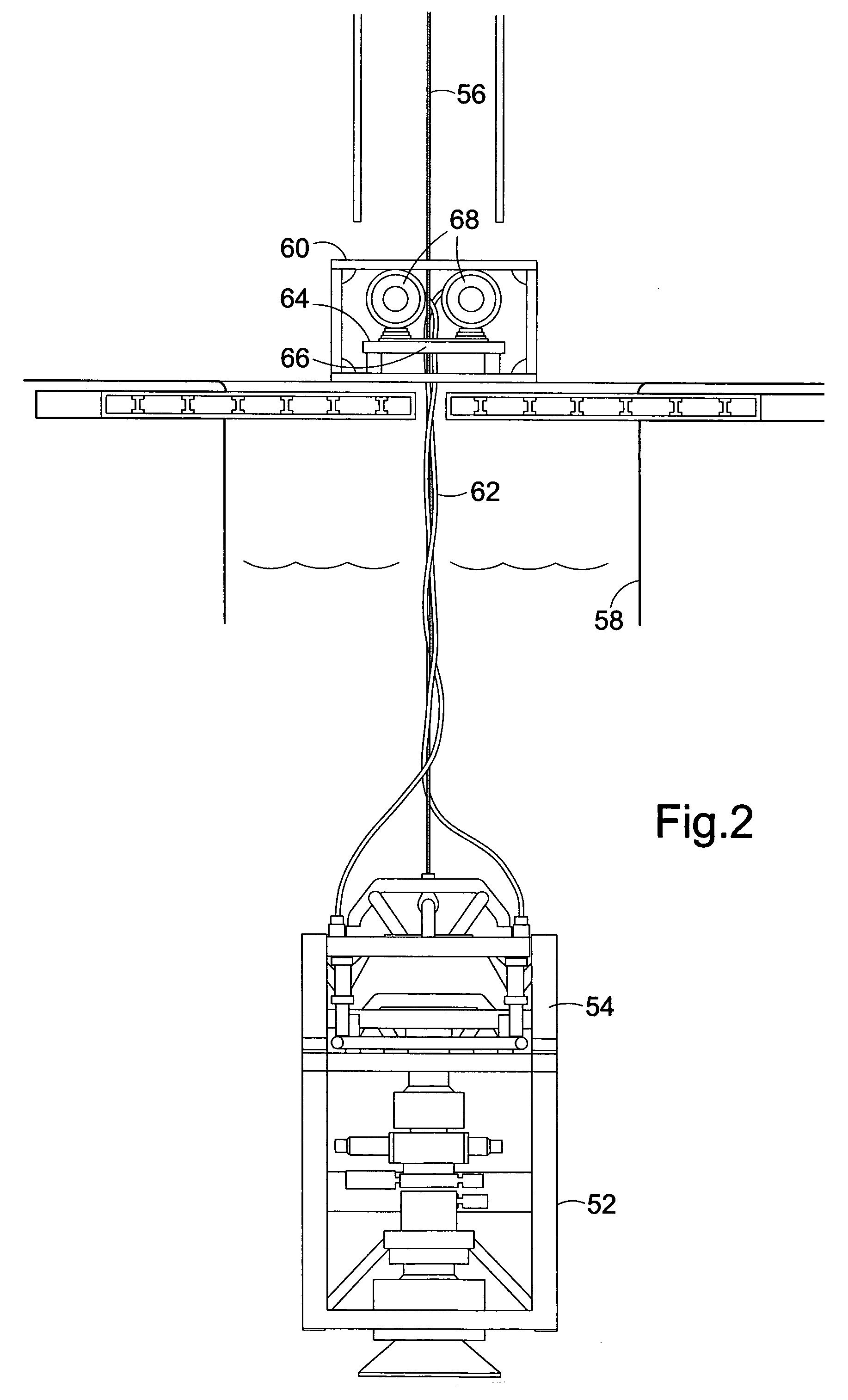
[0126]The system 10 further comprises a first tubular member 22 formed of a length of coiled tubing which extends from a surface vessel 24 and is secured at a lower end thereof to an upper portion of the tool storage package 16 via a latching mechanism 26. In one example, the coiled tubing used to define the first tubular member may describe an outer diameter of ar...


PUM


Abstract

A downhole deployment system comprises a spoolable tubular member (76) adapted to be coupled to a subsea assembly and to extend to surface level. The deployment system also comprises a spoolable support member (96) adapted to extend through the spoolable tubular member (76) and into a wellbore. The spoolable tubular member (76) may define a conduit between the subsea assembly and the surface and the spoolable support member (96) may be utilised to extend through this defined conduit and into a wellbore, for example to deploy a tool into a wellbore, to engage a downhole tool or other object, for example for activation, retrieval or the like.

Description

FIELD OF THE INVENTION[0001]The present invention relates to a deployment system, and in particular, but not exclusively, to a tool deployment system. The tool deployment system may form part of an intervention system.BACKGROUND TO THE INVENTION[0002]There are many well bore operations which require a tool to be delivered into a well bore to the required depth and subsequently be recovered after performing the desired operation. For example, tools may be deployed on wireline, coiled tubing or the like. However, it is often the case that a store of tools are required to be held on site to be ready for use as appropriate, which accordingly takes up valuable space.[0003]Furthermore, many offshore wells are located in water depths exceeding several thousand metres and as such deploying tools through a subsea wellhead and into a wellbore first have to be tripped through the water depth within a marine riser. As such, the proportion of the total tripping time occupied by passing through t...

Claims


Application Information

Patent Timeline
Patent Type & Authority Applications(United States)
IPC IPC(8): E21B19/08E21B41/08E21B17/01B63B35/03
CPCE21B17/015E21B19/006E21B33/076E21B19/143E21B19/22E21B19/008
Inventor SHAND, DAVID MICHAEL
Owner AX S TECH
Why Eureka
Try Eureka