Power apparatus and electronic apparatus using the same

Inactive Publication Date: 2011-01-13
PANASONIC CORP
View PDF14 Cites 24 Cited by
  • Summary
  • Abstract
  • Description
  • Claims
  • Application Information

AI Technical Summary

Benefits of technology

[0007]A power apparatus of the present invention includes a main body case, a plurality of power supply elements provided inside the main body case, and a fire-extinguishing agent tank facing each of the plurality of power supply elements. Between the power supply elements and the fire-extinguishing agent tank facing the power supply elements, an opening part configured to sense heat of each of the power supply element and open the fire-extinguishing agent tank is provided. With such a configuration, the size of the power apparatus can be reduced.
[0008]That is to say, in the present invention, the fire-extinguishing agent tank facing each of the plurality of power supply elements is provided, and the opening part configured to sense heat of each of the power supply element and open the fire-extinguishing agent tank is provided between each of the power supply elements and the fire-extinguishing agent tank facing the power supply elements. Thus, from the fire-extinguishing agent tank in the portion corresponding to the relevant power supply element whose temperature is abnormally increased, a fire-extinguishing agent can be reliably ejected. That is to say, the amount of the fire-extinguishing agent can be reduced as compared with a conventional example in which a fire-extinguishing agent is ejected in a wide area. As a result, the size of the apparatus can be reduced.
[0009]Furthermore, an electronic apparatus of the present invention uses the above-mentioned power apparatus as an electric power supply. Thus, the size of the electronic apparatus can be reduced and the safety can be enhanced.

Problems solved by technology

The problem in the conventional example of the above-mentioned Patent Document 1 is that the size of the power apparatus is increased.
Therefore, when a fire-extinguishing agent is ejected to all parts of the plurality of power supply elements from a nozzle, an extremely large amount of fire-extinguishing agent is necessary, which causes to increase the size of the apparatus.

Method used


Image

  • Power apparatus and electronic apparatus using the same
  • Power apparatus and electronic apparatus using the same
  • Power apparatus and electronic apparatus using the same

Examples


first exemplary embodiment

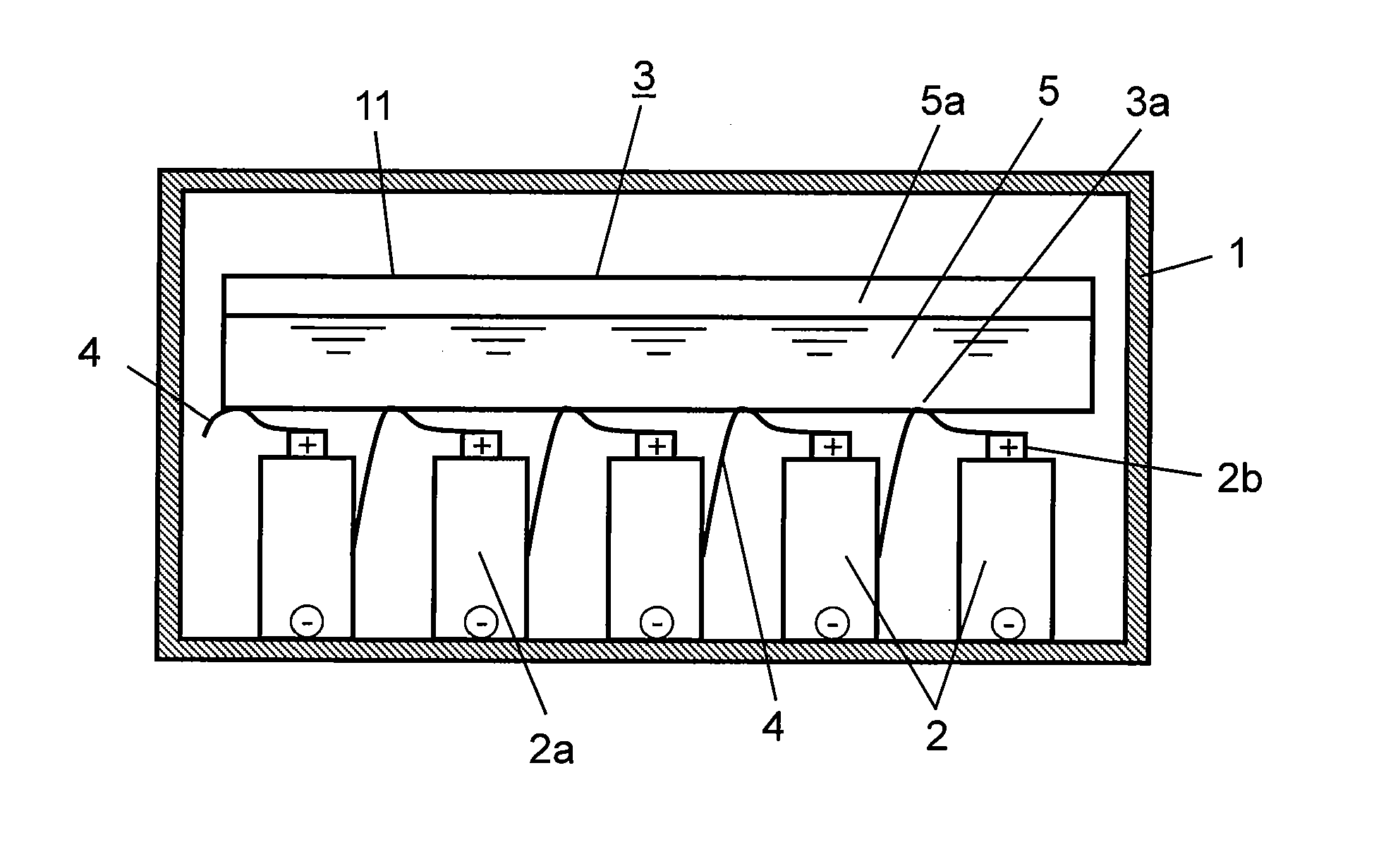
[0045]FIG. 1 is a sectional view showing a power apparatus in accordance with a first exemplary embodiment of the present invention. As shown in FIG. 1, the power apparatus includes main body case 1, a plurality of power supply elements 2 provided inside main body case 1, and horizontally long fire-extinguishing agent tanks 3 each facing each of the plurality of power supply elements 2. Herein, a specific example of the plurality of power supply elements 2 includes a battery or a capacitor. In this exemplary embodiment, batteries are described as an example of power supply elements 2.

[0046]Fire-extinguishing agent tank 3 is made of synthetic resin such as polypropylene which is softened and then melted by heat generated by the temperature rise. As shown in FIG. 1, fire-extinguishing agent tank 3 is a container having a horizontally-long hollow shape, and the inside thereof is filled with fire-extinguishing agent 5 in a pressurized state.

[0047]Note here that fire-extinguishing agent ...

second exemplary embodiment

[0055]Hereinafter, a power apparatus in accordance with a second exemplary embodiment of the present invention is described in detail with reference to FIGS. 2 and 3.

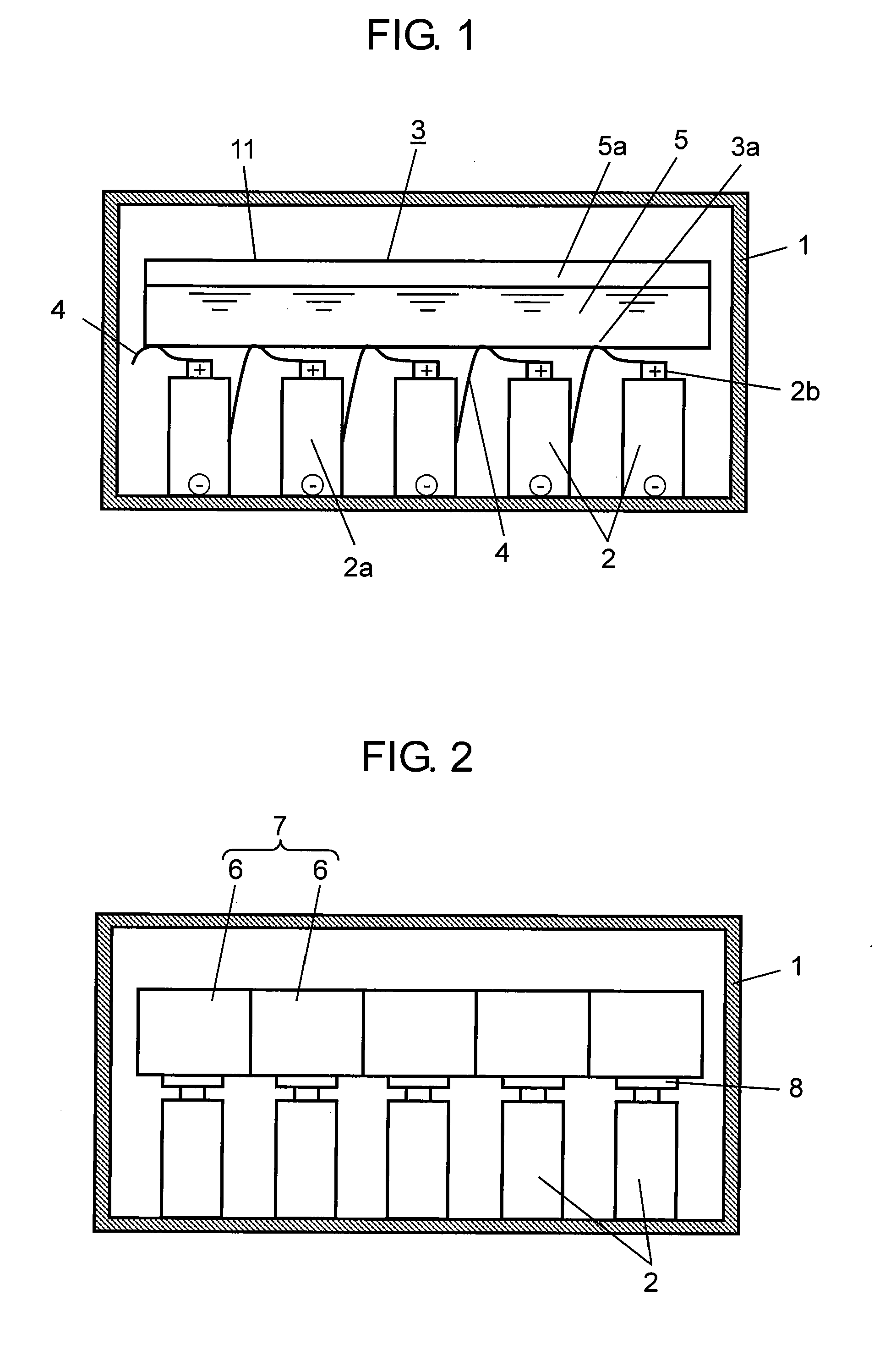
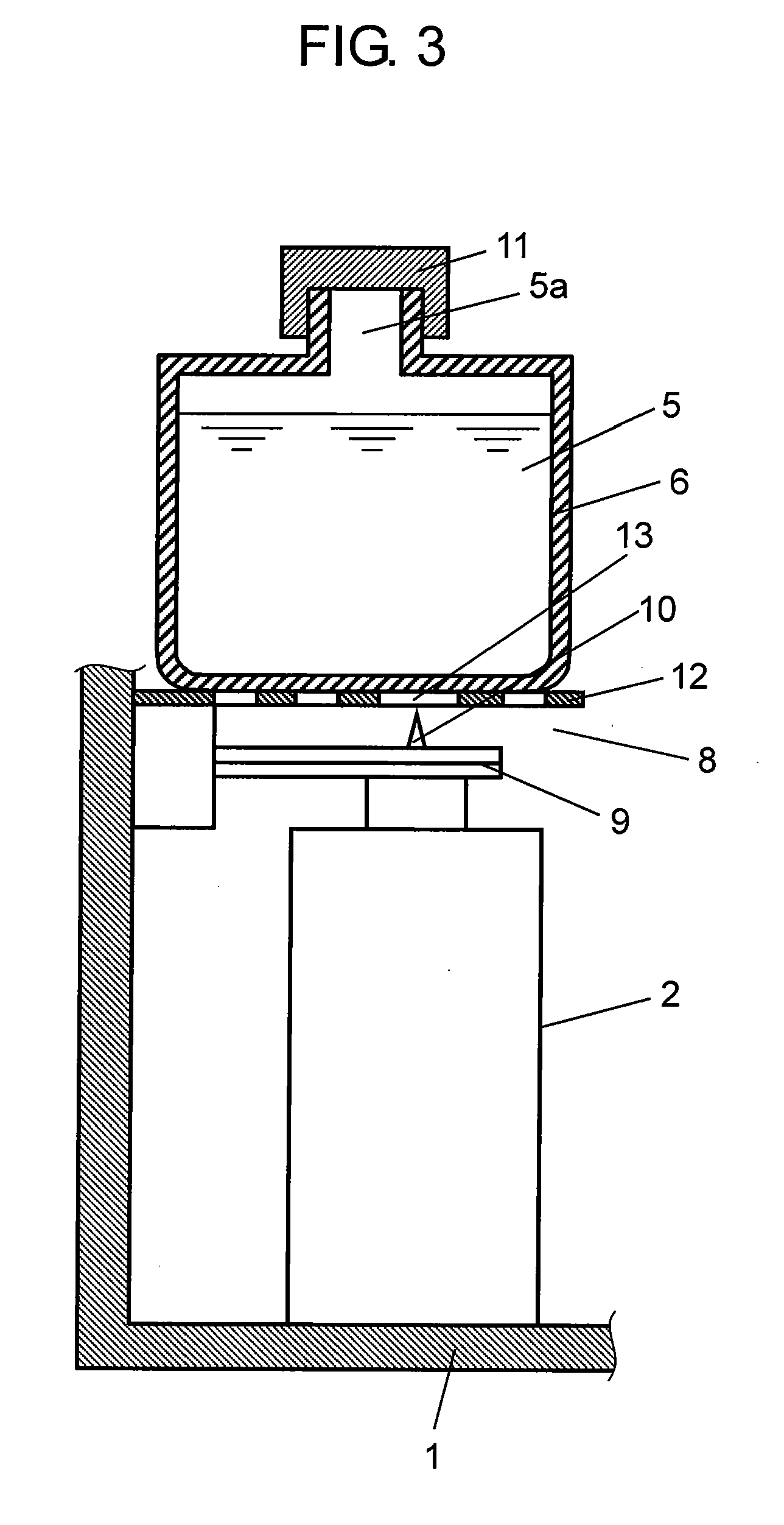
[0056]FIG. 2 is a sectional view showing an electronic apparatus in accordance with the second exemplary embodiment of the present invention. FIG. 3 is an enlarged sectional view of a main portion of the electronic apparatus in accordance with the second exemplary embodiment of the present invention.

[0057]As shown in FIG. 2, the power apparatus of this exemplary embodiment includes main body case 1, a plurality of power supply elements (for example, batteries or capacitors) 2 provided inside main body case 1, and fire-extinguishing part 7 having fire-extinguishing agent tanks 6 each facing respective power supply element 2.

[0058]As shown in FIG. 3, fire-extinguishing part 7 includes independent fire-extinguishing agent tanks 6 facing the upper part of each of power supply elements 2. In this configuration, fire-extingui...

third exemplary embodiment

[0079]Hereinafter, an electronic apparatus in accordance with a third exemplary embodiment of the present invention is described in detail with reference to FIG. 7.

[0080]FIG. 7 is a view showing a configuration of an electronic apparatus in accordance with the third exemplary embodiment of the present invention. As shown in FIG. 7, the power apparatus in accordance with the first or second exemplary embodiment is used as a power supply of an electronic apparatus such as an electric vehicle. Since the configuration and effect of the power apparatus are the same as those in the first or second exemplary embodiment, the description thereof is omitted.

[0081]As shown in FIG. 7, the electronic apparatus in accordance with this exemplary embodiment includes front wheels 24A and rear wheels 24B coupled to axles 23A and 23B, respectively, shaft 25 for linking front wheels 24A and rear wheels 24B to each other, power transmission unit 26 provided on front wheels 24A or rear wheels 24B, motor ...


PUM


Abstract

A power apparatus of the present invention includes a main body case, a plurality of power supply elements provided inside the main body case, and a fire-extinguishing agent tank facing each of the plurality of power supply elements. An opening part for sensing heat of the power supply elements and substantially opening the fire-extinguishing agent tank is provided between the power supply elements and the fire-extinguishing agent tank facing the power supply elements, thus enabling the size to be reduced.

Description

TECHNICAL FIELD[0001]The present invention relates to a power apparatus capable of coping with abnormal circumstances of a power supply element and an electronic apparatus using the power apparatus.BACKGROUND ART[0002]In electronic apparatuses such as automobiles, electric vehicles and the like, in which electric power from a power apparatus drives a drive motor used as a power source, have been developed and have received much attention from the viewpoint of energy saving.[0003]Furthermore, the above-mentioned power apparatus is equipped with a fire-extinguishing agent which is ejected from a plurality of nozzles in the abnormal circumstances in order to enhance the safety in the abnormal circumstances such as collision (see, for example, Patent Document 1).[0004]The problem in the conventional example of the above-mentioned Patent Document 1 is that the size of the power apparatus is increased.[0005]That is to say, the power apparatus has a configuration in which a plurality of po...

Claims


Application Information

Patent Timeline
IPC IPC(8): A62C3/00
CPCB60L3/0046Y02T90/34H01M10/486B60L3/0053B60L58/34B60L58/27Y02T90/40Y02T10/70Y02E60/10A62C3/16
Inventor YASUI, SHUNSUKEHIRAKAWA, YASUSHI
Owner PANASONIC CORP
Why Eureka
Try Eureka