DC machine

a dc machine and support technology, applied in the field of dc machines, can solve the problems of additional noise decoupling between the support and the housing of the brush-holder, and achieve the effect of sufficient stability and tolerance chain of a dc machin

Inactive Publication Date: 2011-01-13
ROBERT BOSCH GMBH
View PDF24 Cites 15 Cited by
  • Summary
  • Abstract
  • Description
  • Claims
  • Application Information

AI Technical Summary

Benefits of technology

[0003]Example embodiments of the present invention provide that the tolerance chain of a DC machine, conditioned upon the production and the assembling of the brush-holder support, is clearly reduced. This particularly achieves that the brush-holder support o

Problems solved by technology

On the other hand, this design additionally yields noise decoupling between the brush-holder support and the

Method used


Image

  • DC machine
  • DC machine
  • DC machine

Examples


Embodiment Construction

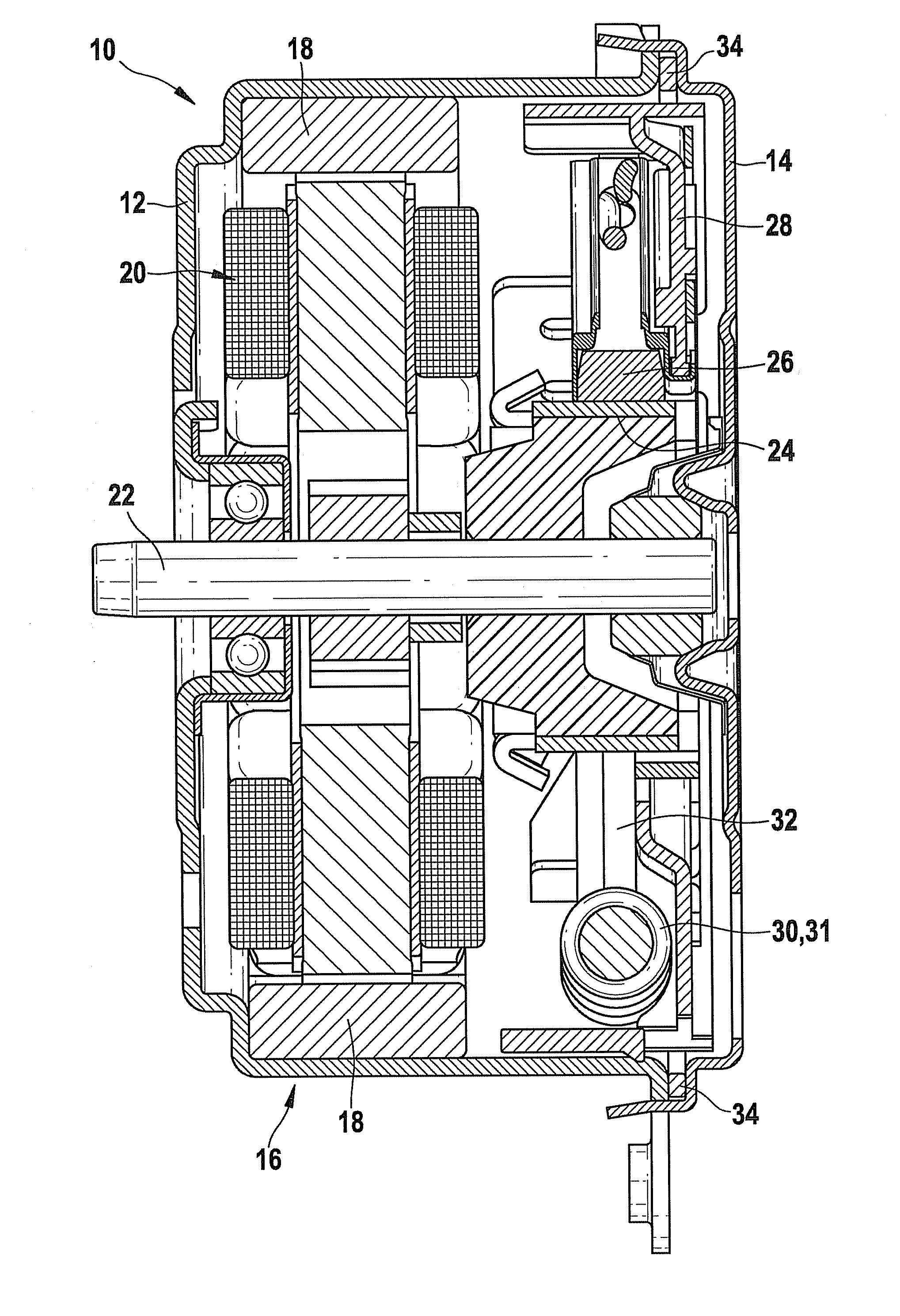
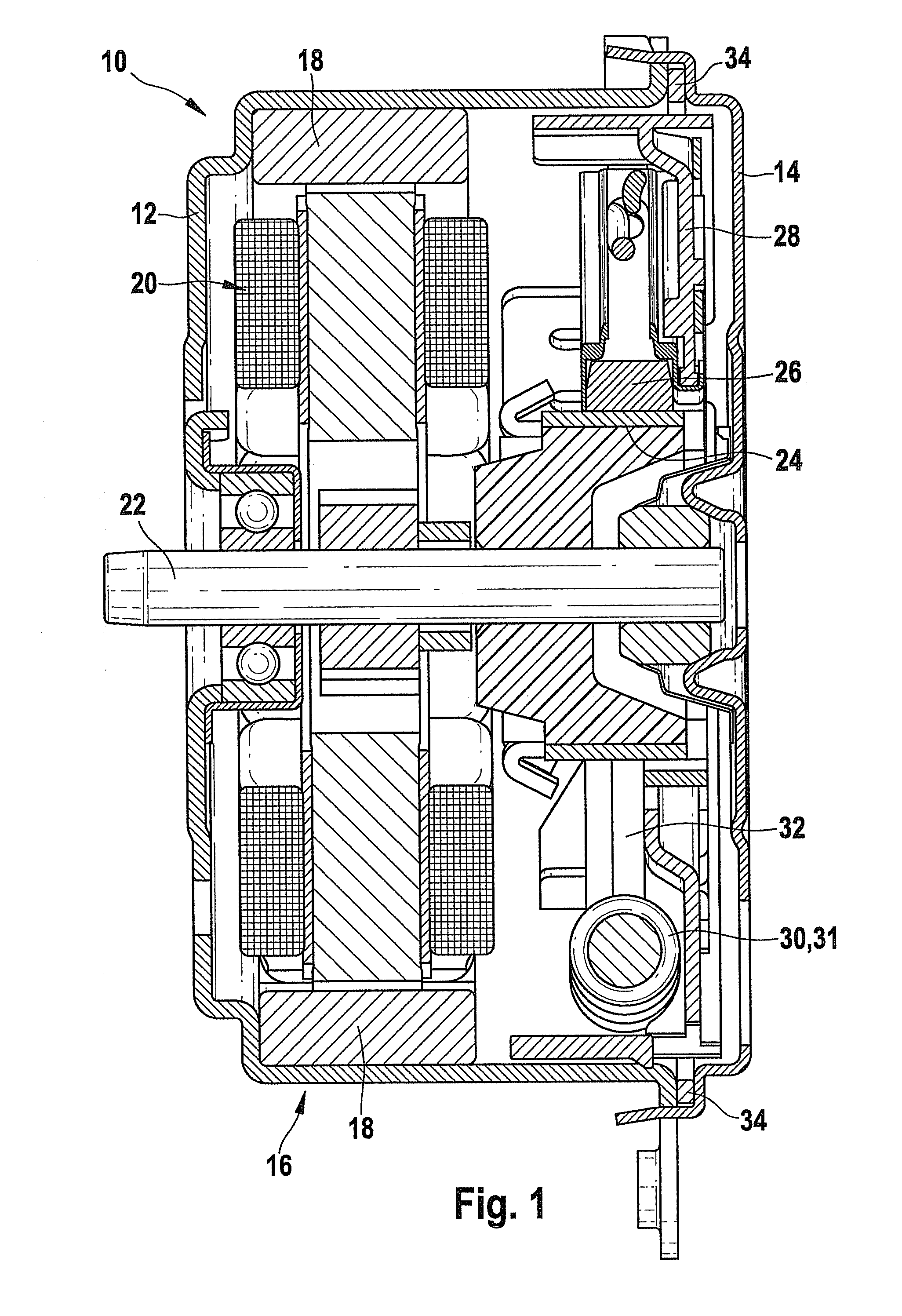
[0017]FIG. 1 shows a DC machine 10 executed as a DC motor for use in a motor vehicle. The machine has a pot-shaped pole housing 12, which is closed on one side by a bearing cover 14. Inside pole housing 12, a stator 16 is developed by permanent magnets 18, which are fastened to pole housing 12 in a known manner. A rotor 20 of the machine is positioned on a shaft 22, which is rotatably supported, on one side in pole housing 12, and on the other side in bearing cover 14. Furthermore, there is a commutator 24 situated on rotor shaft 22, to which the field current for rotor 20 is supplied via brushes 26.

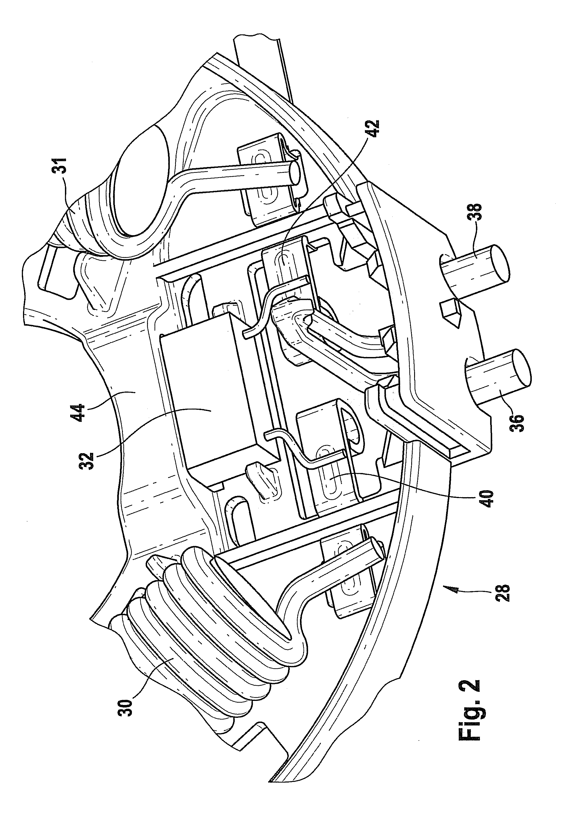
[0018]Brushes 26 and additional components, especially the required interference suppressor of the machine, are held on a brush-holder support 28. Of the interference suppressor of the motor, one may see in FIG. 1 an interference suppression choke 30 and a capacitor 32. The locking of brush-holder support 28 in pole housing 12 takes place by a mounting flange 34, which extends over the e...


PUM


Abstract

A DC machine, particularly a DC motor for use in a motor vehicle, includes a stator, a rotor that is supported rotatably in a pole housing having a commutator, and having a brush-holder support, made substantially of plastic, for fixing at least two brushes and further components. The brush-holder support has a device for improving the positioning of the components situated on or at it relative to the rest of the machine and/or for shortening the tolerance chain of the machine, in particular, a longtime stabilization of the overall equipment being also achieved.

Description

FIELD OF THE INVENTION[0001]The present invention relates to a DC machine, particularly for a DC motor for use in a motor vehicle.BACKGROUND INFORMATION[0002]Such brush-commutated DC machines having a plastic brush-holder support are basically known, for instance, from DE 38 18 891. This document shows a DC machine having a disk-shaped brush-holder support designated there as a base, which is entirely made of plastic and is connected rigidly, in a predefined position with respect to the commutator of the machine, to its pole housing. As to the positioning of components on the brush-holder support of the machine, the document only makes statements with regard to the connection of the brushes, which are electrically connected and fastened to the connecting lines of the machine in a contact piece.SUMMARY[0003]Example embodiments of the present invention provide that the tolerance chain of a DC machine, conditioned upon the production and the assembling of the brush-holder support, is c...

Claims


Application Information

Patent Timeline
IPC IPC(8): H01R39/40H01R39/38H02K11/02
CPCH02K11/026H02K5/148
Inventor SHIN, JAE YONGKOPF, FRANKSCHEIB, OLIVERLIEDEL, MARKUSKUPFERER, MICHAELSTRUPP, MICHAEL
Owner ROBERT BOSCH GMBH
Why Eureka
Try Eureka