Light emitting diode illumination device and method for controlling electric current

a technology of light emitting diodes and illumination devices, which is applied in the direction of electric variable regulation, process and machine control, instruments, etc., can solve the problems of complicated circuit architecture in the whole led lamp body, the flicker phenomenon on the light source is effectively improved, and the cost saving

Inactive Publication Date: 2011-01-13
LEXTAR ELECTRONICS CORP
View PDF4 Cites 54 Cited by
  • Summary
  • Abstract
  • Description
  • Claims
  • Application Information

AI Technical Summary

Benefits of technology

[0008]Therefore, it is a primary objective of the present invention to overcome the aforementioned shortcoming and deficiency of the prior art by providing light emitting diode illumination device capable of effectively improving the flicker phenomenon on the light source and omitting the filter component installed inside each LED lamp body and a method for controlling current.
[0010]Accordingly, the flicker phenomenon on the light source can be effectively improved by increasing frequencies, and the filter component installed inside each LED lamp body can be omitted. More specifically, a simple circuit is used to reliably drive the LED element to achieve goals of rapidly developing products and saving costs.

Problems solved by technology

However, the former manner is too complicated while converting alternating current into direct current; the latter manner may obtain high voltages.
The high voltages may cause dangers, and the capacitor for filtering may have the problem of service life.
Therefore, the capacitor for filtering is installed inside the LED lamp body to cause more complicated circuit architecture in the whole LED lamp body.
Consequently, the speed of developing products may be influenced, and the whole LED lamp body is unable to be normally operated due to damaged capacitors.

Method used


Image

  • Light emitting diode illumination device and method for controlling electric current
  • Light emitting diode illumination device and method for controlling electric current
  • Light emitting diode illumination device and method for controlling electric current

Examples


Embodiment Construction

[0018]The foregoing and other technical characteristics of the present invention will become apparent with the detailed description of the preferred embodiments and the illustration of the related drawings.

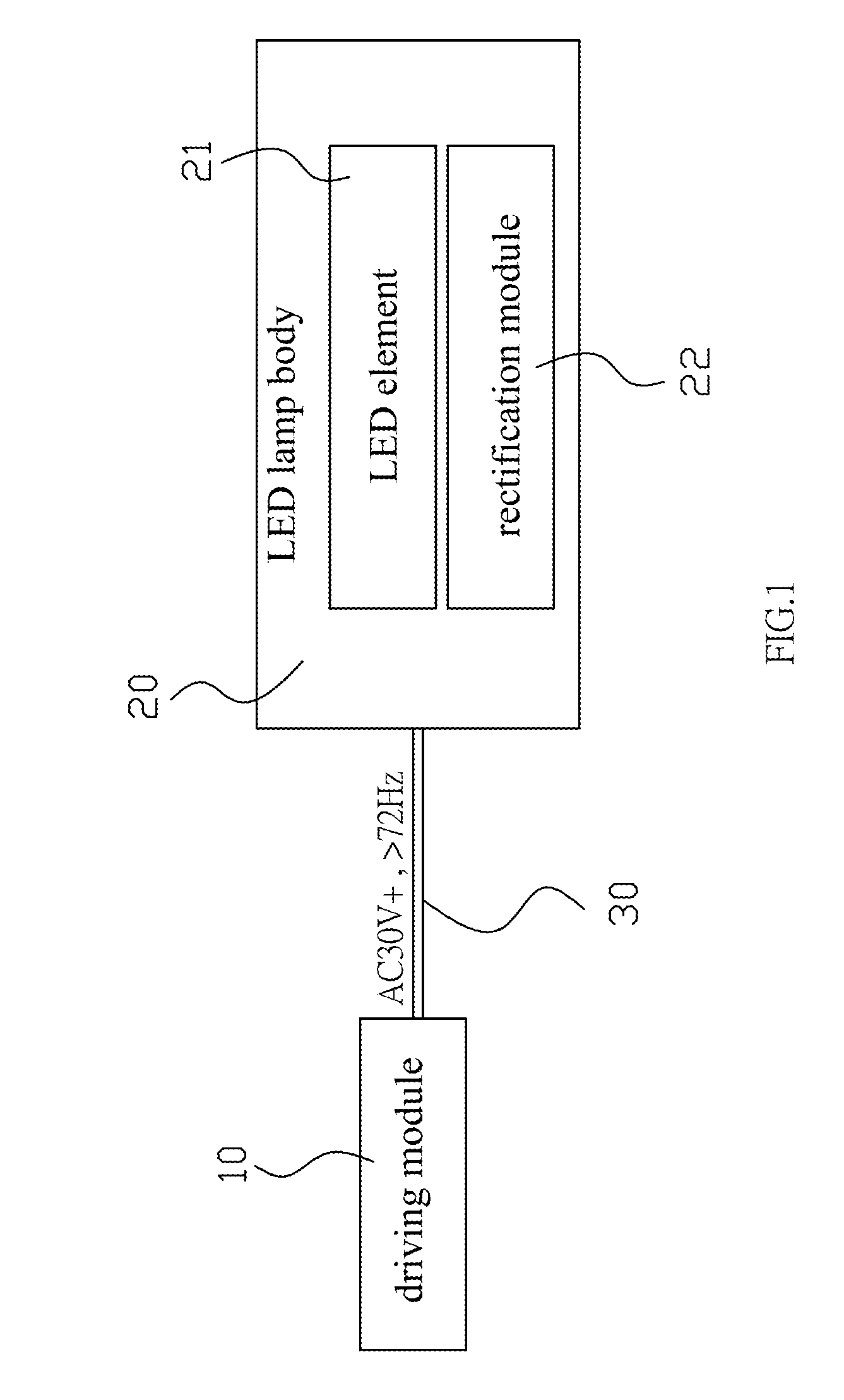
[0019]The objective of the present invention is to provide a LED illumination device capable of effectively improving the flicker phenomenon on the light source and omitting the filter component installed inside each LED lamp body and a method for controlling current. As shown in FIG. 1, the LED illumination device of the present invention comprises a driving module 10, at least one LED lamp body 20 and at least one power transmission line 30.

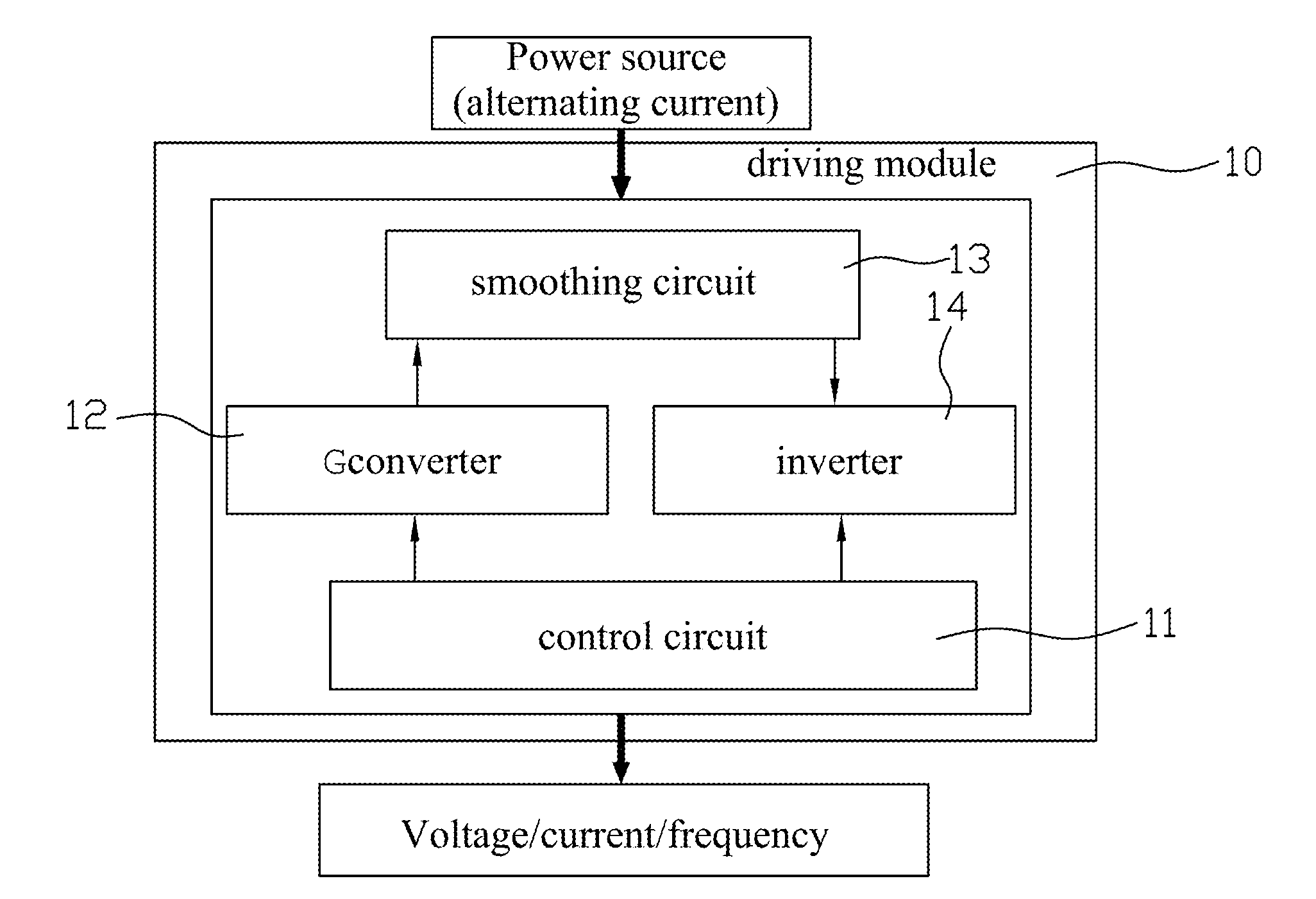
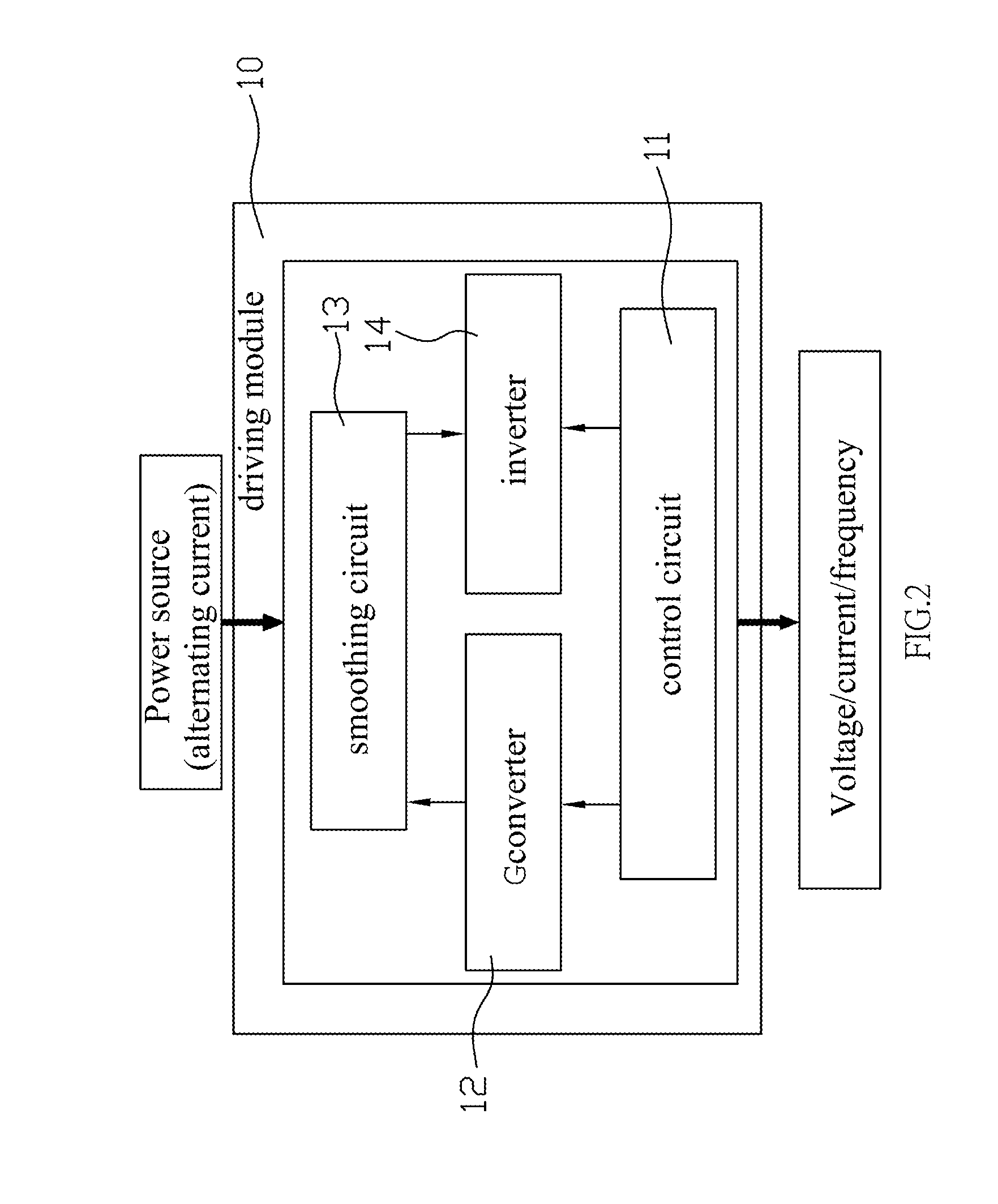
[0020]The driving module 10 is used for outputting a high frequency alternating power having above 30 voltages and above 72 Hz frequencies. While in implementation, a control circuit 11, a converter 12, a smoothing circuit 13 and an inverter 14 are integrated in the driving module 10. With reference to FIG. 2 and FIG. 3, alternating current (...


PUM


Abstract

A light emitting diode (LED) illumination device utilizes a power transmission line to electrically connect a driving module and at least one LED lamp body. The driving module outputs a high frequency alternating power having above 30 voltages and above 72 Hz frequencies through frequency modulation. Each LED lamp body has at least one LED element and a rectification module. The high frequency alternating power generated from the driving module is modulated by the rectification module into a direct power to drive the LED element. Accordingly, the flicker phenomenon on the light source can be effectively improved, and the filter component installed inside each LED lamp body can be omitted. A simple circuit is used to reliably drive the LED element to achieve goals of rapidly developing products and saving costs.

Description

BACKGROUND OF THE INVENTION[0001]1. Field of the Invention[0002]The present invention relates to a light emitting diode illumination device and a method for controlling currents.[0003]2. Description of the Related Art[0004]A light emitting diode (LED) is solid-operated and unlike conventional fluorescent lamp tubes or incandescent lamp bulbs that may be damaged due to gas or vacuum tubes. Further, since the LED has properties of resisting vibrations, swing and abrasion, the service life can be effectively increased. When the value of the LED products is greatly improved, the field of high brightness LED is continuously developed. For illumination markets, the conventional fluorescent lamp tubes or incandescent lamp bulbs will be gradually replaced with the high brightness LEDs that are applied to flashlights, searchlights, camp lights, photo flash light, medical lamps or outdoor lighting.[0005]Moreover, modular LED elements have been presented to the public. People can conveniently ...

Claims


Application Information

Patent Timeline
Patent Type & Authority Applications(United States)
IPC IPC(8): H05B37/02H05B44/00
CPCH05B33/0809H05B45/37Y02B20/30
Inventor WU, MENG-CHAITZOU, HUA-LUNGHSU, CHUN-KAI
Owner LEXTAR ELECTRONICS CORP
Why Eureka
Try Eureka