Ultrathin mutual capacitance touch screen and combined ultrathin touch screen

a capacitance touch screen, ultrathin technology, applied in the direction of instruments, computing, electric digital data processing, etc., can solve the problems of already becoming a restrictive factor and increasing the cost of products

Inactive Publication Date: 2011-01-13
FOCALTECH SYST LTD
View PDF7 Cites 200 Cited by
  • Summary
  • Abstract
  • Description
  • Claims
  • Application Information

AI Technical Summary

Problems solved by technology

Obviously, the layered structure of the mutual capacitance touch screen of the prior art has already become a restrictive factor for the development of touch screens towards ultrathin touch screens.
Furthermore, the electric field distribution of a monolayer touch screen is completely different from that of layered touch screen, thus the methods and structures in the prior art for increasing the effective capacitivity of the layered touch screen are no longer suitable for the monolayer touch screen, and a new method and / or structure need to be designed in order to solve the problem how to effectively increase the effective capacitivity in the monolayer mutual capacitance touch screen.
In addition, the layered touch screen has the disadvantages of complicated manufacturing technique, high requirements for the location accuracy of the driving wires 210′ and the sensing wires 310′ and high requirements for production equipment, materials, technique and process, therefore, product cost is increased, and product yield is influenced to a certain extent.

Method used


Image

  • Ultrathin mutual capacitance touch screen and combined ultrathin touch screen
  • Ultrathin mutual capacitance touch screen and combined ultrathin touch screen
  • Ultrathin mutual capacitance touch screen and combined ultrathin touch screen

Examples


Embodiment Construction

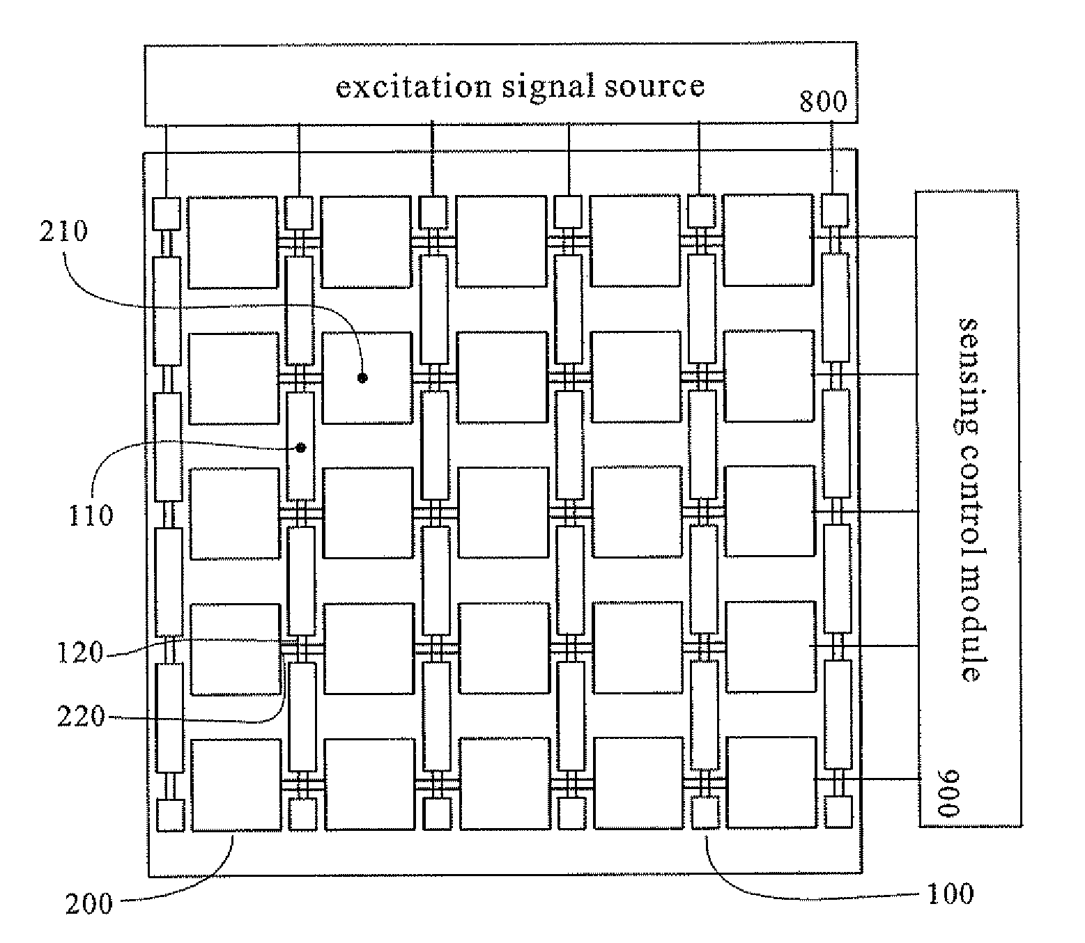
[0050]All the preferred embodiments are further detailed as following in conjunction with figures.

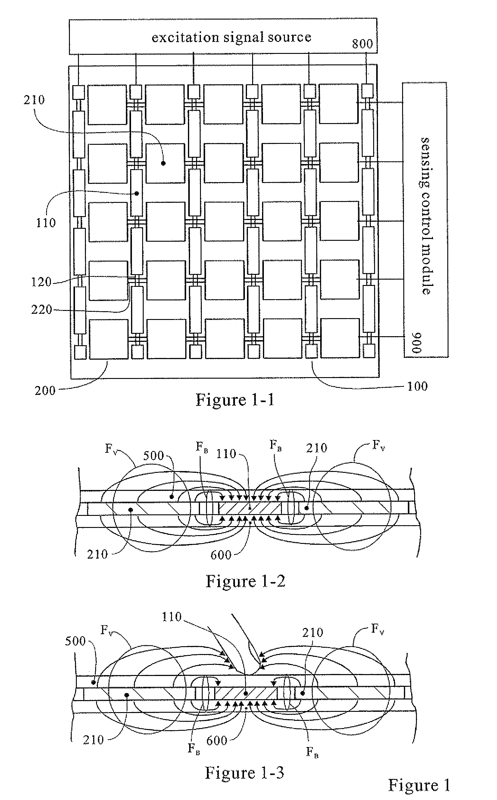
[0051]As mentioned above, the driving wires and the sensing wires of the touch screen in the prior art form two opposite electrode plates of a capacitor. When the driving electrodes and the sensing electrodes are arranged in the same plane, the mutual electric fields among the driving electrodes and the sensing electrodes are totally different from that among the opposite electrodes of the touch screen in the prior art. As shown in FIG. 9, the mutual electric field between a driving electrode 110″ and a sensing electrode 210″ in the same plane comprise an eigen mutual electric field FB which cannot be changed due to the influence of an external conductive electrode and a variable mutual electric field FV which can be changed due to the influence of an external conductive electrode, and the two electric fields respectively form corresponding eigen capacitance CB and variable capacitance ...


PUM


Abstract

Ultrathin mutual capacitance touch screen and combined ultrathin touch screen composed by the said ultrathin mutual capacitance touch screen, the said ultrathin mutual capacitance touch screen comprises driving electrode clusters and sensing electrode clusters, wherein the driving electrode clusters are connected with an excitation signal source arranged outside the touch screen, and the sensing electrode clusters are connected with a sensing control module arranged outside the touch screen. The driving electrode clusters comprise tabulate driving electrodes which are made of transparent conductive materials and connected in series and/or in parallel, and the sensing electrode clusters comprise tabulate sensing electrodes which are made of transparent conductive materials and connected in series and/or in parallel. In particular, in a pair of adjacent driving electrode and sensing electrode of the touch screen, the plate area of at least one electrode producing the eigen mutual electric field is smaller than that of the same electrode producing the variable mutual electric field. The present invention make the thickness of the touch screen become thinner, and ensure a higher effective capacitivity.

Description

TECHNICAL FIELD[0001]The present invention relates to a touch sensing input device, in particular a touch input device using mutual capacitance as a sensing element.BACKGROUND ART[0002]Touch screen is a widely used touch sensing input device. In accordance with the touch sensing principle, the touch screens of the prior art comprise resistive touch screens, capacitive touch screens, infrared surface touch screens and the like, wherein the resistive touch screens are popular for years because of the advantages of low cost, easy realization, simple control and the like. In recent years, capacitive touch screens become popular because of the advantages of high light transmittance, resistance to abrasion, resistance to ambient temperature change, resistance to ambient humidity change, long service life and good capability of realizing high and complex functions such as multipoint touch.[0003]The sensing principle of change in capacitance is long-standing. In order to make the touch scre...

Claims


Application Information

Patent Timeline
Patent Type & Authority Applications(United States)
IPC IPC(8): G06F3/044
CPCG06F3/044G06F3/0443G06F3/0446G06F3/0448
Inventor MO, MICHAELZHANG, JK
Owner FOCALTECH SYST LTD
Why Eureka
Try Eureka