Liquid crystal display device

Inactive Publication Date: 2011-01-13
PANASONIC LIQUID CRYSTAL DISPLAY CO LTD +1
View PDF12 Cites 12 Cited by
  • Summary
  • Abstract
  • Description
  • Claims
  • Application Information

AI Technical Summary

Benefits of technology

[0015]In the present invention, it is possible to provide a liquid crystal display device which has an optical anisotropic coated film made from a coating material containing a dichroic dye exhibiting lyotropic liqu

Problems solved by technology

That is, the arrangement of the dye molecules is disrupted, leading to time-dependent deterioration of the optical a

Method used


Image

  • Liquid crystal display device
  • Liquid crystal display device
  • Liquid crystal display device

Examples


embodiment 1

[0023](Whole Configuration)

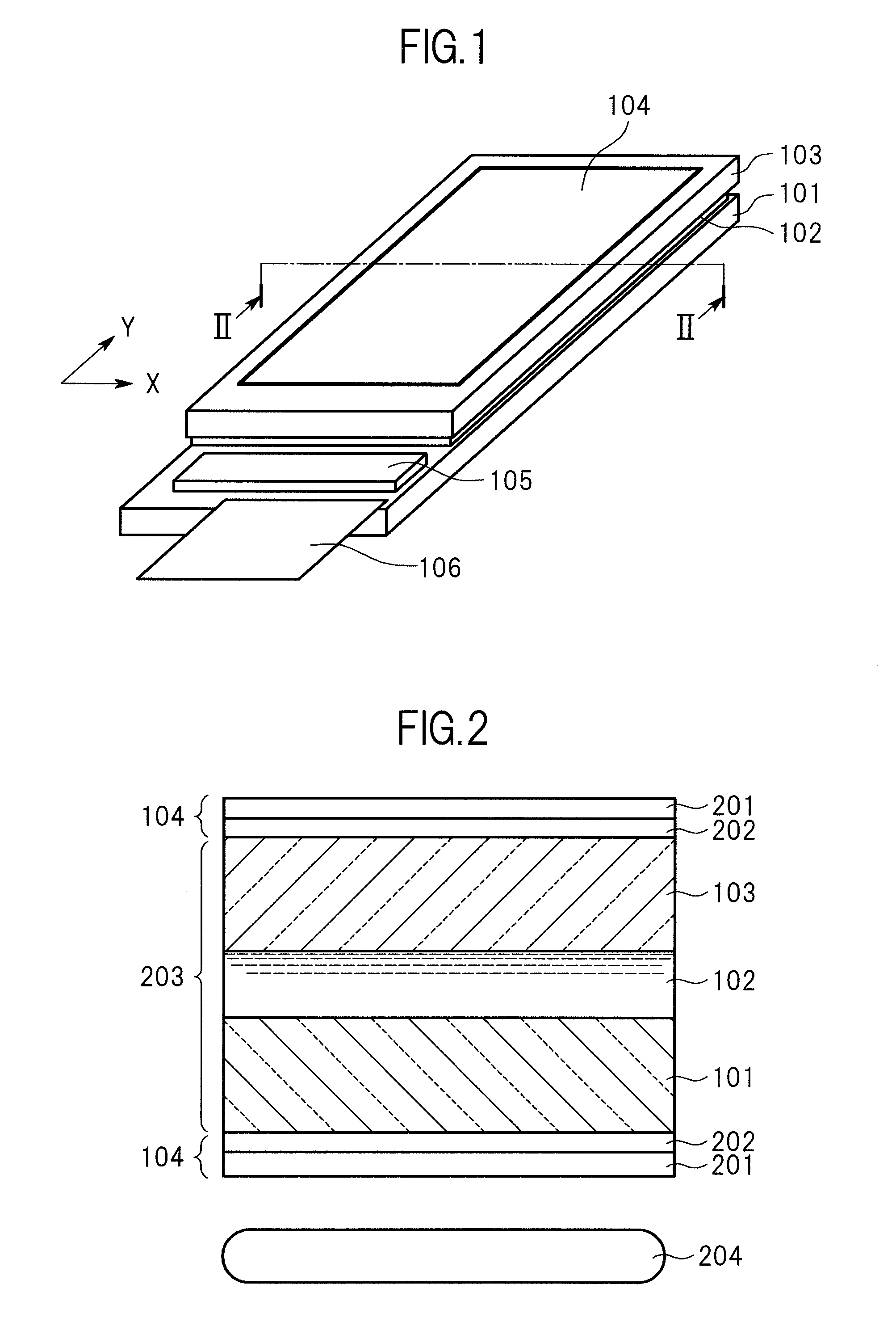
[0024]FIG. 1 is a perspective view for illustrating a schematic configuration of the liquid crystal display device of Embodiment 1 of the present invention. It should be noted that X and Y in the figure represent the X direction and the Y direction, respectively.

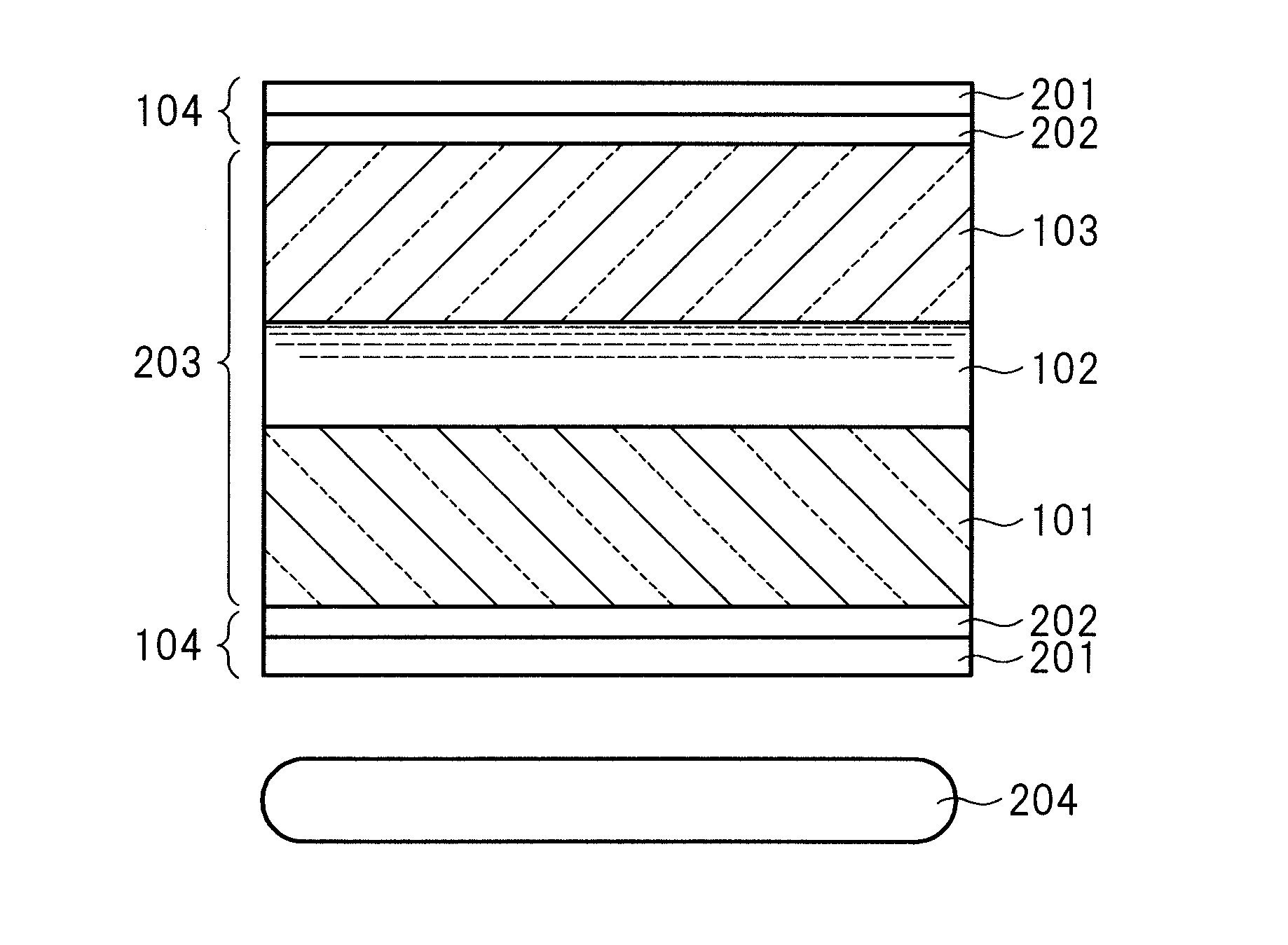
[0025]As illustrated in FIG. 1, the liquid crystal display device of Embodiment 1 has a liquid crystal display panel which is formed of a first substrate (thin-film transistor circuit substrate) 101 on which a pixel electrode and the like are formed, a second substrate (color filter substrate) 103 on which a color filter and a black matrix (light shielding film) are formed and which is arranged opposite to the first substrate 101, and a liquid crystal (liquid crystal layer) 102 interposed between the first substrate 101 and the second substrate 103, and the liquid crystal display device is formed by combining the liquid crystal display panel with a backlight unit serving as a light source and not b...

example 1

[0060]The liquid crystal display device of Example 1 of the present invention was produced under the following conditions. The production method for the device is described using FIG. 1 and FIG. 2.

[0061]The liquid crystal display device in Example 1 is a device obtained by forming, as an optical anisotropic thin film 104, an optical anisotropic coated film 201 made from a coating material containing a dichroic dye exhibiting lyotropic liquid crystallinity and being represented by the following chemical formula (3).

[0062]A mixed solution of pure water and ethanol (mixed ratio is 8 to 2) having a dye solid content concentration of 18% by weight was prepared.

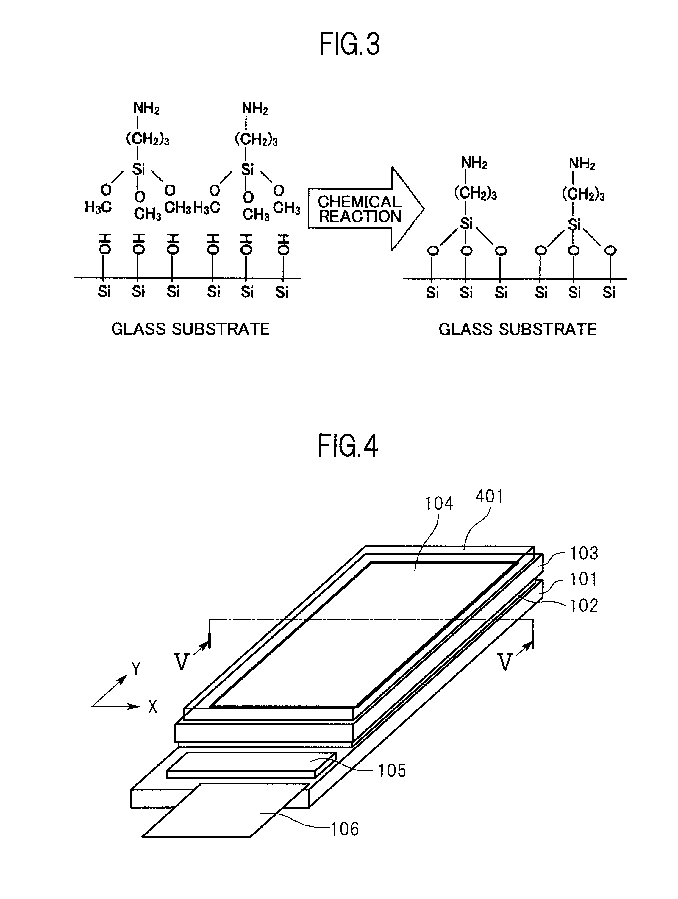
[0063]An organosilicon compound was used to perform a surface treatment on an outer surface of each of glass substrates of a liquid crystal cell 203. Here, with respect to the dye represented by the chemical formula (3), 3-aminopropyltrimethoxysilane was used as the organosilicon compound so that the surfaces of the glass substrate...

example 2

[0071]An optical anisotropic thin film 104 was formed in Example 2 of the present invention in the same conditions as those in Example 1, except that the dye having sulfonic acid groups and being represented by the chemical formula (4) was used in place of the dye represented by the chemical formula (3) in Example 1, and then a liquid crystal display device was produced.

[0072]In the liquid crystal display device provided with the optical anisotropic thin film 104 formed as described above, the interfacial bonding between a dye molecule layer as the lower layer of an optical anisotropic coated film 201 where the molecules of dichroic dyes are regularly arranged and the surfaces of liquid crystal cell glass substrates (first substrate and second substrate) is strengthened, and as a result, the bonding acts as an alignment-controlling force, and functions on the whole dichroic dye molecule layer laminated on the dye molecule layer as the lower layer, enabling the strong retention of th...


PUM


Abstract

Provided is a liquid crystal display device including a liquid crystal panel including: a first substrate on which a plurality of drain lines and a plurality of gate lines are formed, the plurality of gate lines crossing the plurality of drain lines; a second substrate which is arranged opposite to the first substrate via a liquid crystal; and an optical anisotropic film formed on a side of one of the first substrate and the second substrate, the side not being in contact with the liquid crystal; in which a region surrounded by the plurality of drain lines and the plurality of gate lines serves as a pixel region, in which the optical anisotropic film is formed of molecules which chemically bond to one of the first substrate and the second substrate in an aligned state.

Description

CROSS-REFERENCE TO RELATED APPLICATION[0001]The present application claims priority from Japanese application JP2009-161321 filed on Jul. 8, 2009, the content of which is hereby incorporated by reference into this application.BACKGROUND OF THE INVENTION[0002]1. Field of the Invention[0003]The present invention relates to a liquid crystal display device, in particular, a liquid crystal display device having an optical anisotropic coated film made from a coating material containing a dichroic dye exhibiting lyotropic liquid crystallinity as a substitution for an optical anisotropic film used in a liquid crystal display device.[0004]2. Description of the Related Art[0005]Liquid crystal display devices have such advantages as being thinner, requiring a smaller space, being lighter in weight, and consuming less electricity, and are finding wider applications in display devices of various electronic instruments such as televisions, computers, mobile phones, small portable instruments, and...

Claims


Application Information

Patent Timeline
IPC IPC(8): G02F1/1335H01L33/00
CPCC09B7/00C09K19/60C09K19/601C09K19/603G02B5/3016G02F2202/36G02F1/133528G02F1/13363G02F2001/133633G02F2201/50G02F2202/043G02B5/3083G02F1/133633
Inventor TANAKA, JUNOTANI, MIHARUADACHI, MASAYAHIRATSUKA, TAKATO
Owner PANASONIC LIQUID CRYSTAL DISPLAY CO LTD
Why Eureka
Try Eureka