
Network system and monitoring node

a network system and monitoring node technology, applied in the field of network system and monitoring node, can solve the problems of user throughput, reduced increased network delay, etc., and achieve the effect of improving throughput in the whole system

Inactive Publication Date: 2011-01-13
HITACHI LTD
View PDF14 Cites 7 Cited by
  • Summary
  • Abstract
  • Description
  • Claims
  • Application Information

AI Technical Summary

Benefits of technology

The invention is about a system that can efficiently use multiple wireless systems based on the radio conditions of each user's terminal. The system calculates the expected throughput and delay time for each user when they connect to a new wireless system. It also monitors the throughput and delay time of each user and predicts if the quality of communication will improve by changing the wireless system. This way, the system can assign the appropriate wireless system to each user based on their radio environments, improving the overall throughput of the system.

Problems solved by technology

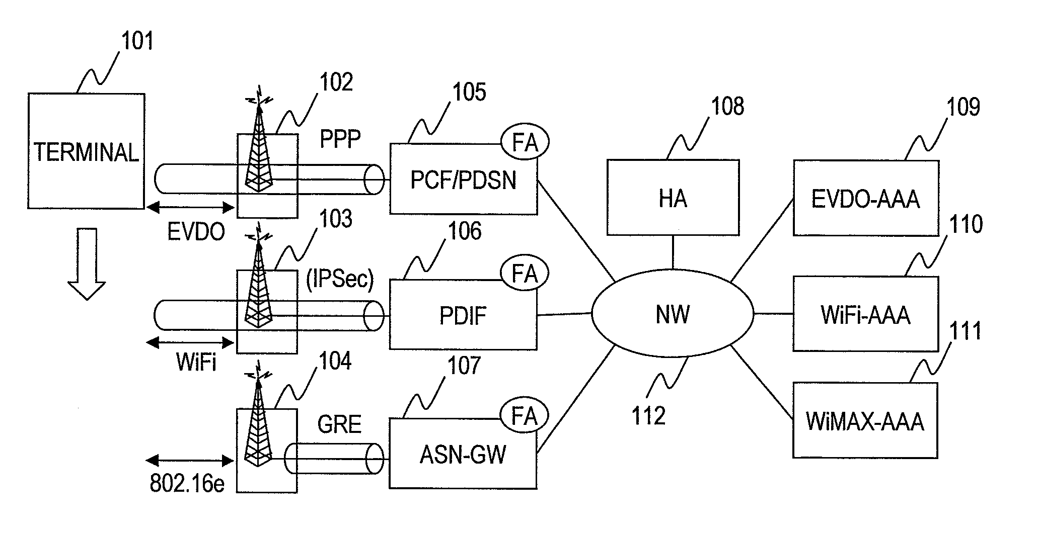
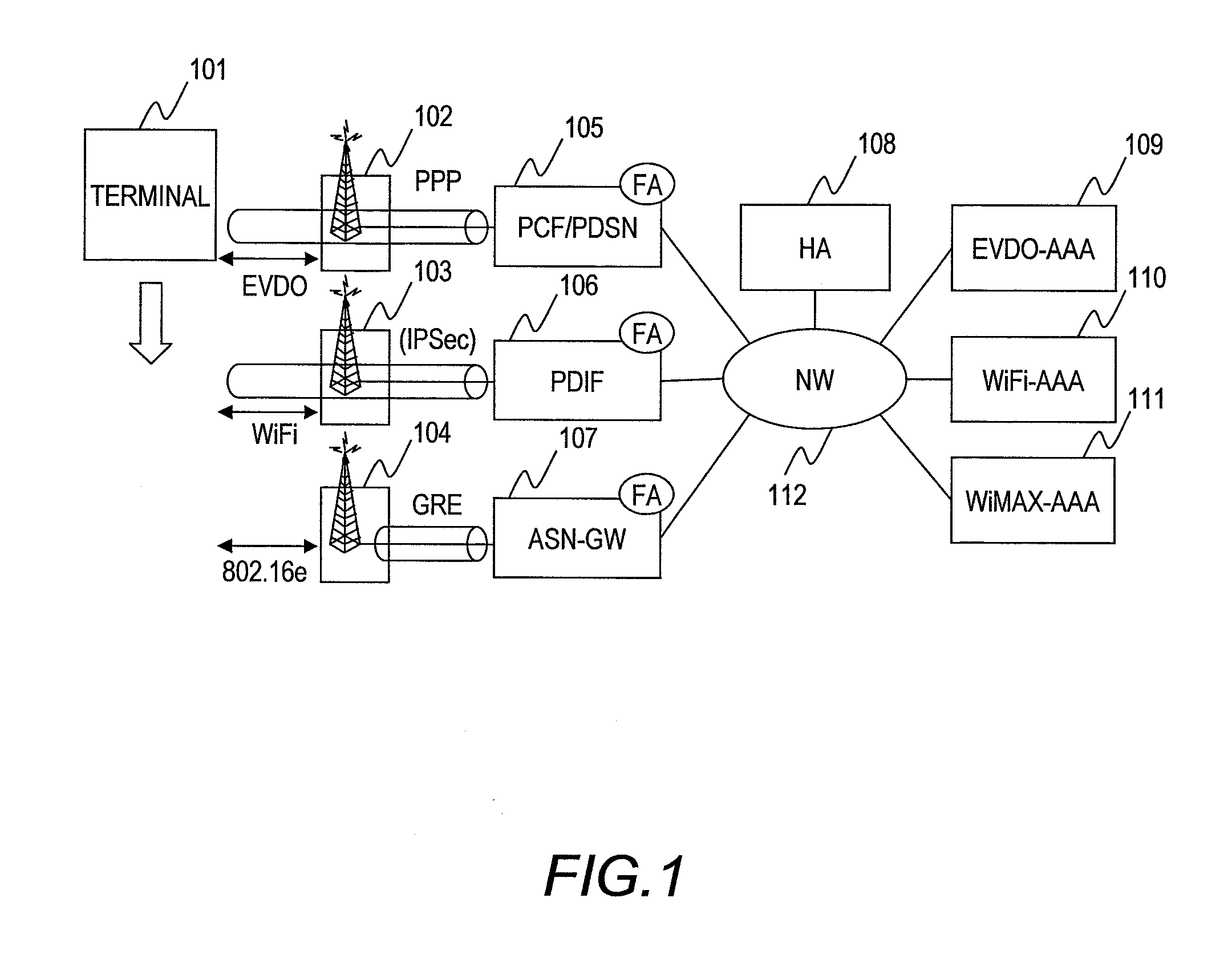
In the conventional system, there has been a problem that, when a terminal newly uses another wireless system in a radio environment where a plurality of wireless systems are available for use, connecting to the wireless system on the user terminal's initiative causes the throughput to exceed the maximum value offered by the wireless system; consequently, the communication bandwidth requested by the terminal cannot be used, and further, the throughputs of the users who had used the wireless system until that time are affected so that the throughput in the whole system is reduced.
In addition, there has been another problem that even if the quality of communication in the wireless system used by a user terminal is degraded because of a change in the radio environment caused by, for example, a move of the user terminal, the conventional system continues to use the same wireless system as long as the session is not interrupted; thereby, the reduction in user throughput increases network delay.

Method used


Image

  • Network system and monitoring node
  • Network system and monitoring node
  • Network system and monitoring node

Examples


first embodiment

A first embodiment of this invention will be described. In this embodiment, when a terminal changes wireless systems, the wireless system to be connected from the terminal is determined so as to maximize the system throughput.

FIG. 4 illustrates a configuration of a system in this invention. To grasp the radio conditions of different wireless systems, the system comprises a monitoring node (CMT: Cognitive Monitoring Tool) (404) which collects information about radio from an access point in each wireless system. The information about radio includes received power values, RSSI values, throughputs of users, transmission rate, transmission delay time, packet loss rate, the number of terminals accommodated in an access point, the number of associations with a terminal, processing load at an access point. With respect to EVDO, values of parameters used for scheduling in a wireless zone, such as DRC values and RRI values, are also included in the radio information.

Further, the monitoring no...

second embodiment

Hereinafter, a second embodiment in the present invention will be described. In this embodiment, when the terminal changes wireless systems, the system to be connected from the terminal is determined so that the delay time will be the minimum.

Similarly to the first embodiment, this embodiment employs the system configuration shown in FIG. 4. A wireless system determination process when a terminal AT0 tries to change the connected system from WiMAX to another system will be described.

FIG. 11 illustrates a wireless system determination process by the monitoring node. A part of the steps in the process shown in FIG. 11 are the same as those in FIG. 5; they are denoted by the same reference numerals. The wireless system determination process is triggered when the terminal AT0 tries to change the currently connected WiMAX into another wireless system. Instead of the terminal's changing the wireless system to another, another terminal's try to start connecting to the system may be the tri...

third embodiment

A third embodiment of this invention will be described. In this embodiment, the monitoring node periodically monitors the throughput of each terminal, and if it detects a decrease in the throughput, it determines whether to change the wireless system to accomplish efficient use of communication bandwidth in the whole system.

Similarly to the first embodiment, this embodiment employs the system configuration shown in FIG. 4. The monitoring node periodically measures the throughputs of all of the terminals currently connecting to the system to determine whether to change the wireless system in each terminal.

FIG. 17 illustrates a process of determining the change of the wireless system by the monitoring node. A part of the steps in the process shown in FIG. 17 is the same as those in FIG. 5; they are denoted by the same reference numerals. First, the monitoring node initializes the threshold value of received power and the maximum throughput in each wireless system (1701). Then, it chec...


PUM


Abstract

In order to improve throughput in a whole network system, there is provided a network system controlling a plurality of wireless systems, comprising: access points of the respective wireless systems; gateways for terminating the respective wireless systems; a certificate authority; a home agent; a monitoring node; a control node; and terminal device connects to the plurality of wireless systems, wherein the monitoring node connects to the access points in the respective wireless systems and obtains information about the terminal device, the control node changes the wireless systems to which the terminal device connects in accordance with instructions of the monitoring node; and the terminal device selects one of the plurality of the wireless systems to which the terminal device connects in accordance with the information about the terminal device obtained by the monitoring node.

Description

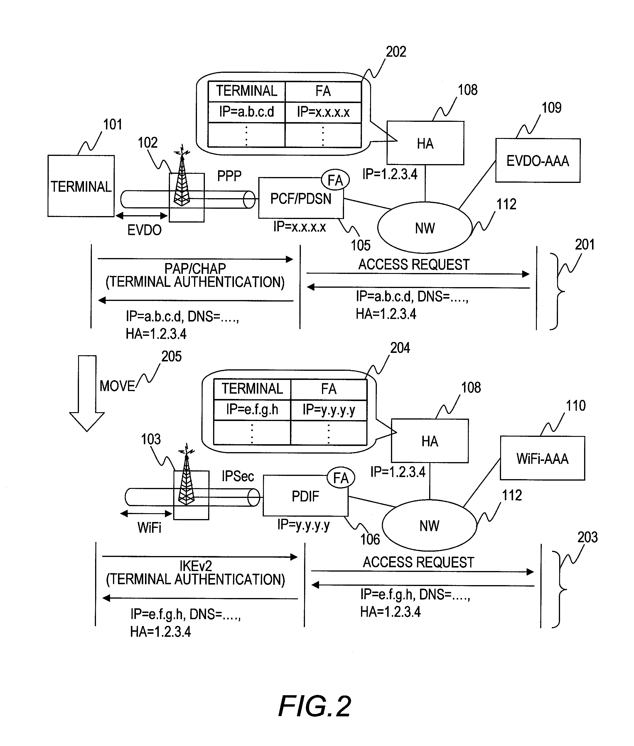
BACKGROUND OF THE INVENTIONThis invention relates to a technique of changing wireless communication systems at higher speed, and cognitive radio technology for improving the time use efficiency of frequency.Nowadays, systems such as the third generation mobile phone systems and the wireless LAN systems are individually operated and managed by individual companies. To use the plurality of systems, it is necessary to subscribe to the systems with their respective companies. In such a case, since the systems are independent in the individual companies, the IP addresses of terminals, which are requisite for network connection, are given to the respective systems independently. Therefore, to use a plurality of systems simultaneously, it has been common to use the systems with a plurality of IP addresses.However, the frequency band below 6 GHz (the VHF, UHF, and low microwave bands) convenient for mobile communication systems is now used densely by the third generation mobile phones, wire...

Claims


Application Information

Patent Timeline
Patent Type & Authority Applications(United States)
IPC IPC(8): H04L12/26H04W4/00
CPCH04W12/06H04W36/30H04W36/14H04W12/61H04W36/1446H04W36/304
Inventor KATAOKA, MIKIOHANAOKA, SEISHI
Owner HITACHI LTD
Learn More