
Transmission control method, network element, base station and radio network controller

a technology of radio network controller and transmission control method, which is applied in the direction of network traffic/resource management, digital transmission, data switching network, etc., can solve the problems of reducing the throughput of the system of the end user, and the inability to fully utilize statistical multiplexing, so as to achieve less capacity, less capacity, less capacity

Inactive Publication Date: 2005-12-15
NOKIA SOLUTIONS & NETWORKS OY
View PDF14 Cites 4 Cited by
  • Summary
  • Abstract
  • Description
  • Claims
  • Application Information

AI Technical Summary

Benefits of technology

The invention provides a method for controlling overbooking of non real-time users in a communication system. By estimating the peak rate of connections carrying information packets with non real-time traffic and reserving a predetermined amount of capacity for them, the system can ensure stability and recovery after an overload, enabling higher user throughput. The invention also provides a way to separate non real-time traffic from real-time traffic, allowing for separate queues and better utilization of network resources.

Problems solved by technology

The interface between a controlling unit of a radio communication system and a base station, called lub in WCDMA (wideband code division multiple access), is often a capacity bottleneck of the radio communication system due to transmission capacity consumption and related costs.
Even though ATM as a technology provides means for statistical multiplexing, the statistical multiplexing cannot be fully utilized due to the real-time behaviour of the interface and due to a protocol operating over it.
In high capacity packet switched data transmission connections (e.g. for web browsing) it is possible that only few users can reserve the whole capacity of the system, which leads to the reduced end user throughput in the system.

Method used


Image

  • Transmission control method, network element, base station and radio network controller
  • Transmission control method, network element, base station and radio network controller
  • Transmission control method, network element, base station and radio network controller

Examples


Embodiment Construction

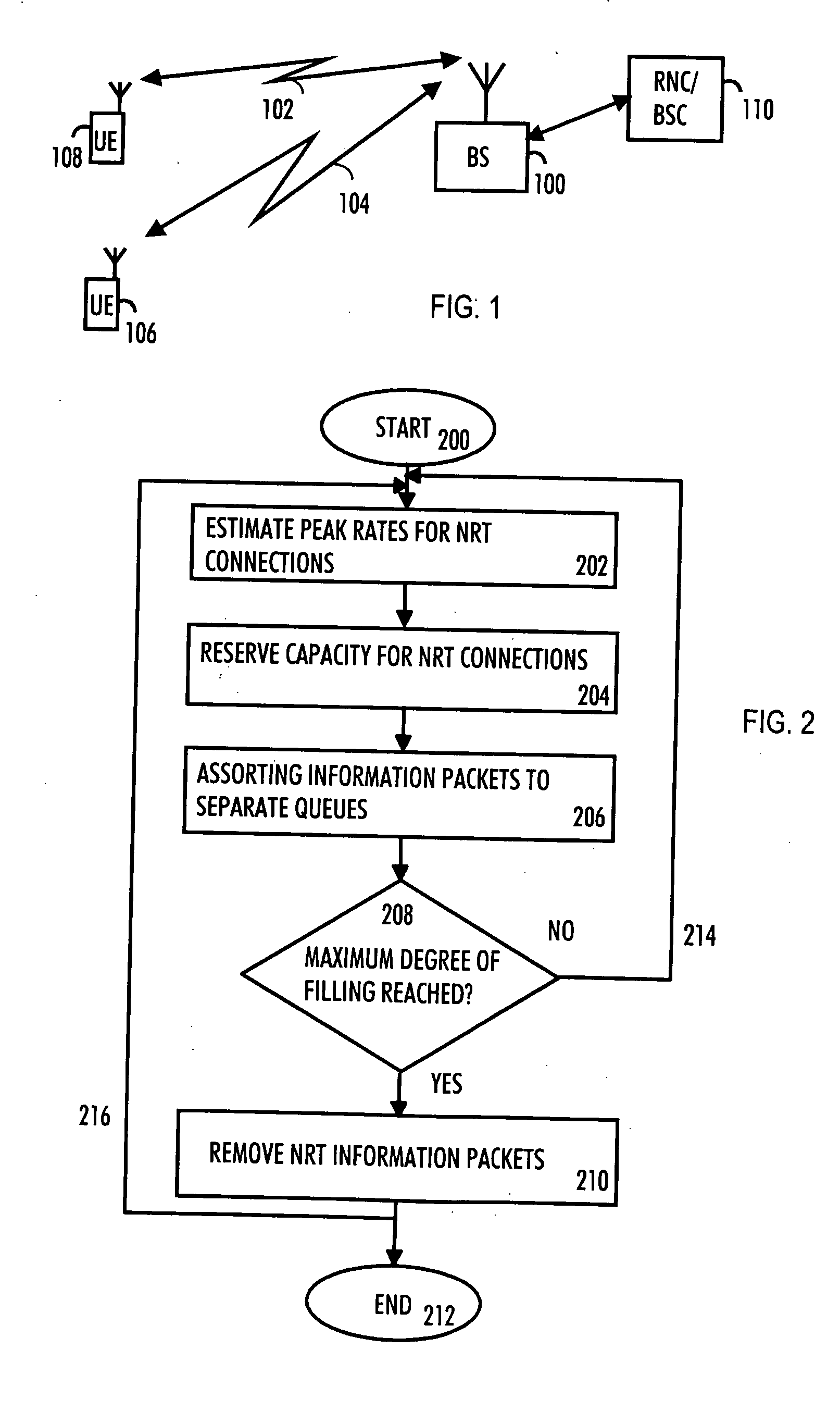
[0018] With reference to FIG. 1, we examine an example of a communication system to which embodiments of the invention can be applied. The present invention can be applied to various wireless communication systems. One example of such a communication system is a UMTS (Universal Mobile Telecommunications System) radio access network. It is a radio access network, which includes WCDMA (wideband code division multiple access) technology and can also offer real-time circuit and packet switched services. The embodiments are not, however, restricted to the systems given as examples but a person skilled in the art may apply the solution to other radio systems provided with the necessary properties.

[0019] It is clear to a person skilled in the art that the method according to the invention can be applied to systems utilizing different modulation methods or air interface standards.

[0020]FIG. 1 is a simplified illustration of a digital data transmission system to which the solution accordin...


PUM


Abstract

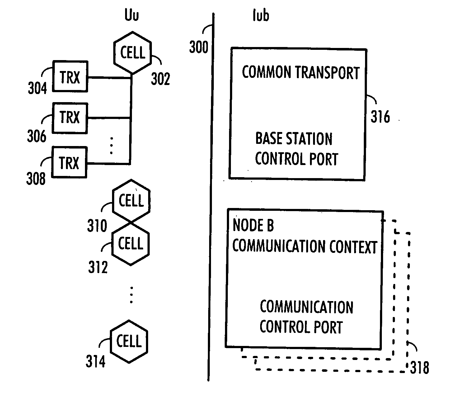
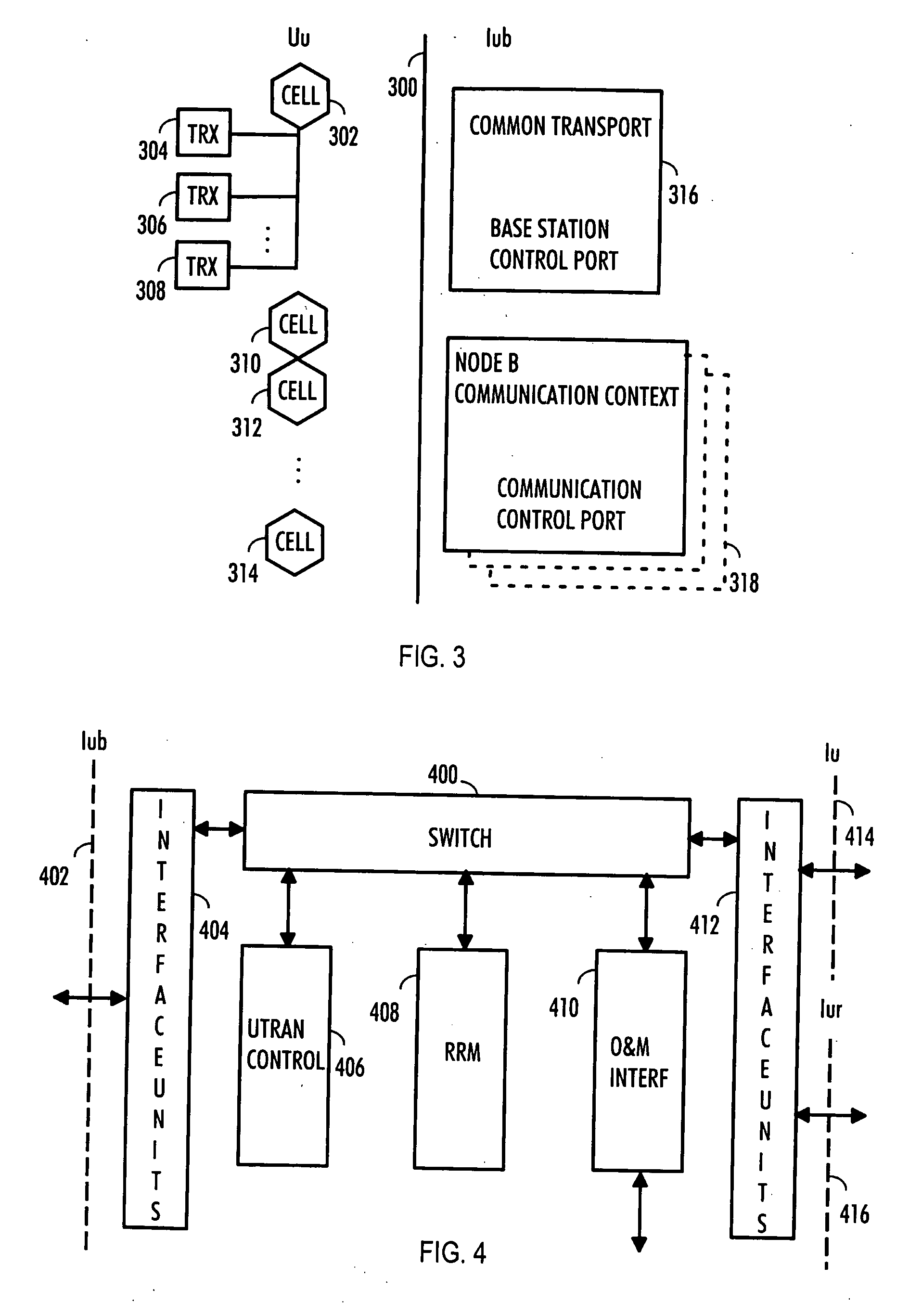
A network element of a communication system comprises, for instance, means (316, 410) for reserving, for connections carrying information packets with non real-time traffic, a predetermined amount less of capacity than the estimated peak rate; means (316, 410) for assorting the information packets with non real-time traffic and information packets with real-time traffic to separate queues, means (316, 410) for removing information packets with non real-time traffic from said non real-time traffic queue.

Description

FIELD [0001] The invention relates to a transmission control method, a network element, a base station and a radio network controller. BACKGROUND [0002] In several communication systems, core network transportation is based on ATM (asynchronous transfer mode). ATM is a transmission procedure based on asynchronous time division multiplexing typically using fixed-length data packets. ATM is usually used for high-speed transportation and switching of various types of data, voice and video signals. [0003] The interface between a controlling unit of a radio communication system and a base station, called lub in WCDMA (wideband code division multiple access), is often a capacity bottleneck of the radio communication system due to transmission capacity consumption and related costs. Even though ATM as a technology provides means for statistical multiplexing, the statistical multiplexing cannot be fully utilized due to the real-time behaviour of the interface and due to a protocol operating...

Claims


Application Information

Patent Timeline
Patent Type & Authority Applications(United States)
IPC IPC(8): H04LH04L47/2416H04L47/30H04L47/32H04W28/10H04W28/26H04W92/12
CPCH04L47/10H04L47/12H04L47/14H04L47/2416H04L47/2441H04W92/12H04L47/32H04L2012/5607H04L2012/5653H04W28/10H04W28/26H04L47/30H04W28/02H04W8/04
Inventor METSALA, ESAMAJOR, TAMAS
Owner NOKIA SOLUTIONS & NETWORKS OY
Learn More