System communication systems and methods for electric vehicle power management

a technology of communication system and electric vehicle, applied in the field of electric vehicles, can solve the problems of inability to quickly replace other devices, inability to quickly replace either device, and inability to meet the requirements of the application, and achieve the effect of reducing the consumption of traffic traversing

Inactive Publication Date: 2011-01-13
GRIDPOINT
View PDF3 Cites 93 Cited by
  • Summary
  • Abstract
  • Description
  • Claims
  • Application Information

AI Technical Summary

Benefits of technology

[0007]In one embodiment, a system for minimizing network traffic consumption in a power flow management system includes devices operable to generate, consume, or store electric energy, and a power flow management system, which manages power flow transferred between the plurality of devices and a power grid. This minimization system also includes a network to communicate device information and power flow information between the power flow management system and the devices. The device information is received by the power flow management system. The power flow information is transmitted by the power flow management system, and includes an energy rate command received by a devices. The power flow management system reduces consumption of the traffic traversing the network via a network traffic consumption reduction technique.

Problems solved by technology

Considering the very long service life of items such as utility meters and automobiles, the use of multiple incompatible protocols may pose an barrier to deployment.
For example, if a homeowner buys a car that utilizes one protocol and receives a utility meter that uses another protocol, it is unlikely that either device will quickly replace other device.
In addition to cost of translating messages, there is a cost associated with transmitting messages across networks.

Method used


Image

  • System communication systems and methods for electric vehicle power management
  • System communication systems and methods for electric vehicle power management
  • System communication systems and methods for electric vehicle power management

Examples


Embodiment Construction

[0024]Reference will now be made in detail to the embodiments of the present invention, examples of which are illustrated in the accompanying drawings.

[0025]Overview

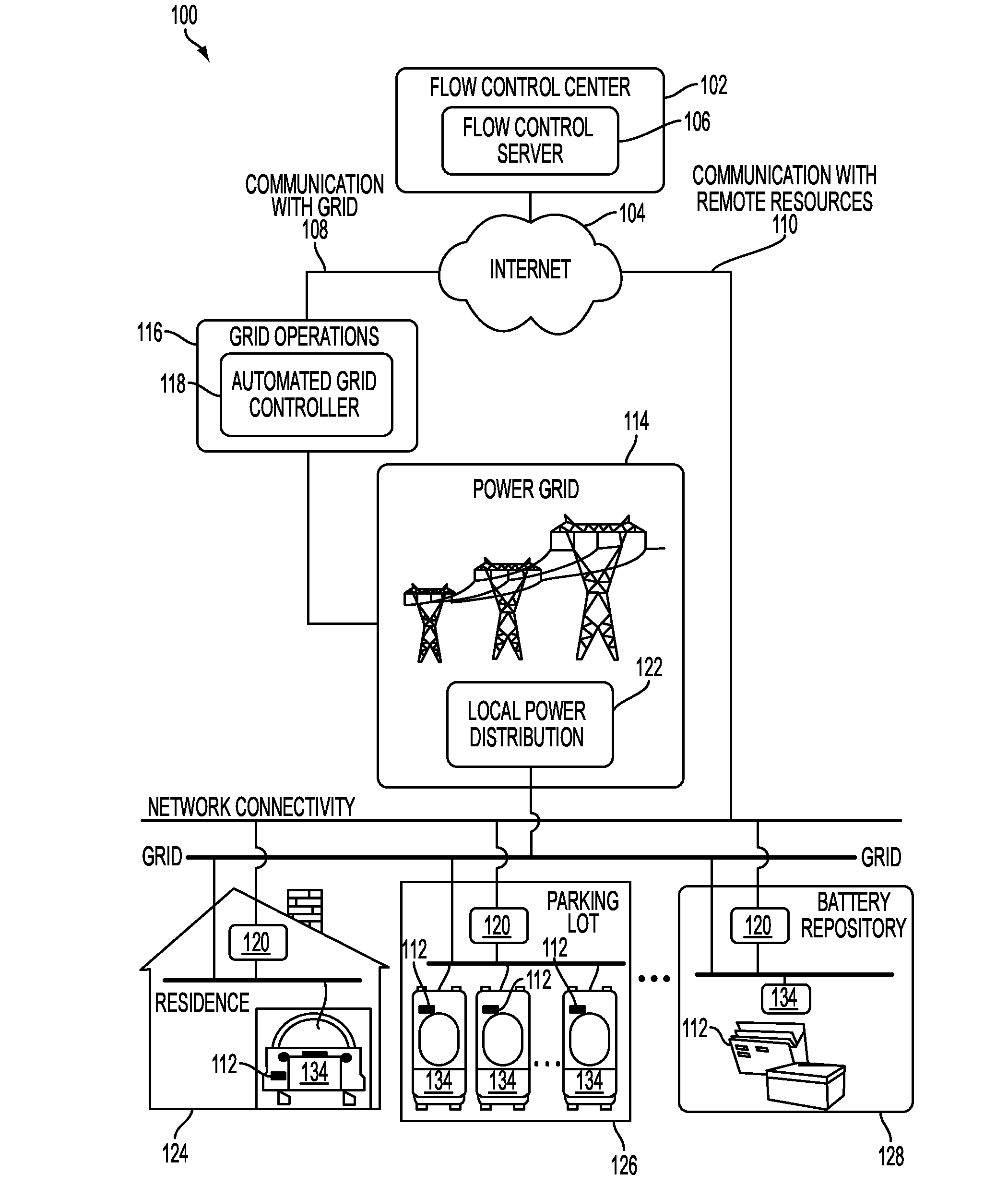
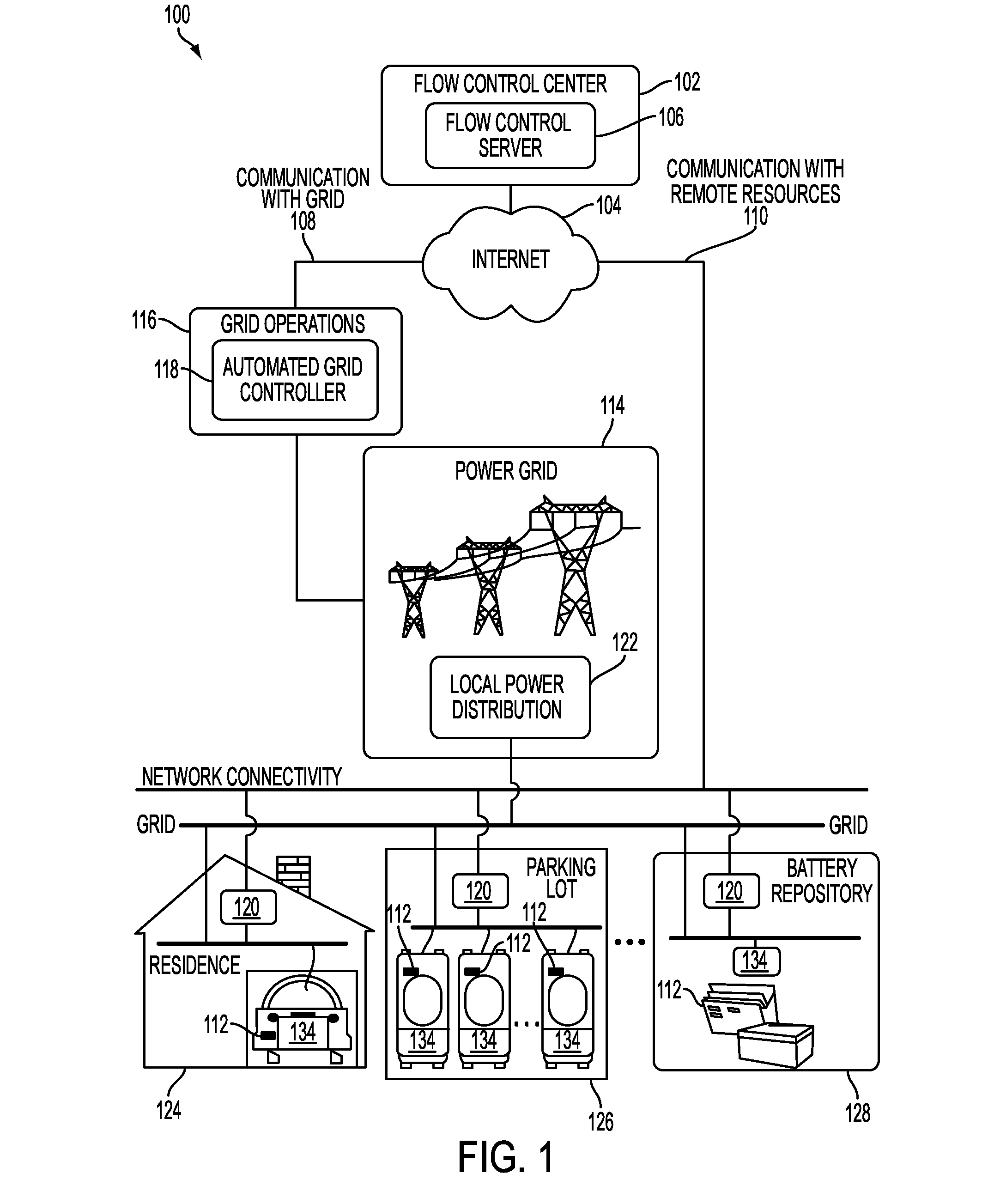
[0026]Described herein is a power aggregation system for distributed electric resources, and associated methods. In one implementation, a system communicates over the Internet and / or some other public or private networks with numerous individual electric resources connected to a power grid (hereinafter, “grid”). By communicating, the system can dynamically aggregate these electric resources to provide power services to grid operators (e.g. utilities, Independent System Operators (ISO), etc).

[0027]“Power services” as used herein, refers to energy delivery as well as other ancillary services including demand response, regulation, spinning reserves, non-spinning reserves, energy imbalance, reactive power, and similar products.

[0028]“Aggregation” as used herein refers to the ability to control power flows into and out of a s...


PUM


Abstract

A system and method that minimizes network traffic consumption in a power flow management system is described. A minimization system may include a network to communicate device information and power flow information between the power flow management system and the devices. The power flow management system reduces consumption of the traffic traversing the network via a network traffic consumption reduction technique. In addition, this application discloses a system and method for communications protocol translation in a power flow management system that includes networks which connect electric devices and electric power supplies. One network utilizes a communications protocol that is different from the communications protocol utilized by another network. A communications protocol translation device communicates with the networks, and formulates messages from one communications protocol to the other communications protocol. The reformulated messages pass from one network to another network.

Description

[0001]This non-provisional patent application claims priority to, and incorporates herein by reference, U.S. Provisional Patent Application No. 61 / 165,344 filed on Mar. 31, 2009. This application also incorporates herein by reference the following: U.S. patent application Ser. No. 12 / 252,657 filed Oct. 16, 2008; U.S. patent application Ser. No. 12 / 252,209 filed Oct. 15, 2008; U.S. patent application Ser. No. 12 / 252,803 filed Oct. 16, 2008; and U.S. patent application Ser. No. 12 / 252,950 filed Oct. 16, 2008.[0002]This application includes material which is subject to copyright protection. The copyright owner has no objection to the facsimile reproduction by anyone of the patent disclosure, as it appears in the Patent and Trademark Office files or records, but otherwise reserves all copyright rights whatsoever.FIELD OF THE INVENTION[0003]The present invention relates in general to the field of electric vehicles, and in particular to novel systems and methods for system communication a...

Claims


Application Information

Patent Timeline
Patent Type & Authority Applications(United States)
IPC IPC(8): H04B3/00H02J3/14
CPCY02T10/7005Y02T90/16Y02T90/163Y02T90/169Y02T90/14Y02T90/128Y02T90/121Y04S30/14Y02E60/721B60L11/1842H02J3/381H02J7/0052Y04S10/126B60L2240/70B60L53/64B60L55/00B60L53/63B60L53/65B60L53/665B60L53/305B60L53/18B60L53/68H02J2300/10Y02E60/00Y02T10/7072Y02T10/70Y02T10/72Y02T90/12Y02T90/167Y04S30/12G05D29/00H02J7/00
Inventor BRIDGES, SETH W.LAFKY, JOBY
Owner GRIDPOINT
Why Eureka
Try Eureka