Receiving apparatus and method

a technology of receiving apparatus and receiving method, which is applied in the direction of line-faulst/interference reduction, amplitude demodulation, pulse technique, etc., can solve the problems of significant performance degradation, interference from other transmission antennas, and multipaths of desired transmission antenna signal, etc., and achieve optimal equalization performance

Active Publication Date: 2011-01-13
NEC CORP
View PDF3 Cites 19 Cited by
  • Summary
  • Abstract
  • Description
  • Claims
  • Application Information

AI Technical Summary

Benefits of technology

[0061]It is therefore an object of the present invention to provide a MIMO receiving apparatus and a MIMO receiving method that transforms a single carrier signal into a frequency domain signal and that performs processing for equalization by signal processing in the frequency domain, in which it is possible to improve an equalization performance.
[0068]Thus, in a method and an apparatus for transforming a single carrier signal into a frequency domain signal and for doing equalizing processing by signal processing in the frequency domain, the residual interference due to interference from other transmission antennas and to multipath interference are used according to the present invention for correction of the likelihood of an equalized signal, thereby realizing optimum equalization performance.

Problems solved by technology

If the MIMO multiplexing system is used for a single carrier signal, not only the interference from other transmission antenna, but also the multipaths of a desired transmission antenna signal forms interferences.
However, if multipath interference resulting from other transmission antennas and from multipaths should increase, performance is degraded significantly due to noise amplification caused by equalization and to residual multipath interference.
This solution may not be realistic in consideration of increase in the computational load or in the processing delay.

Method used


Image

  • Receiving apparatus and method
  • Receiving apparatus and method
  • Receiving apparatus and method

Examples


Embodiment Construction

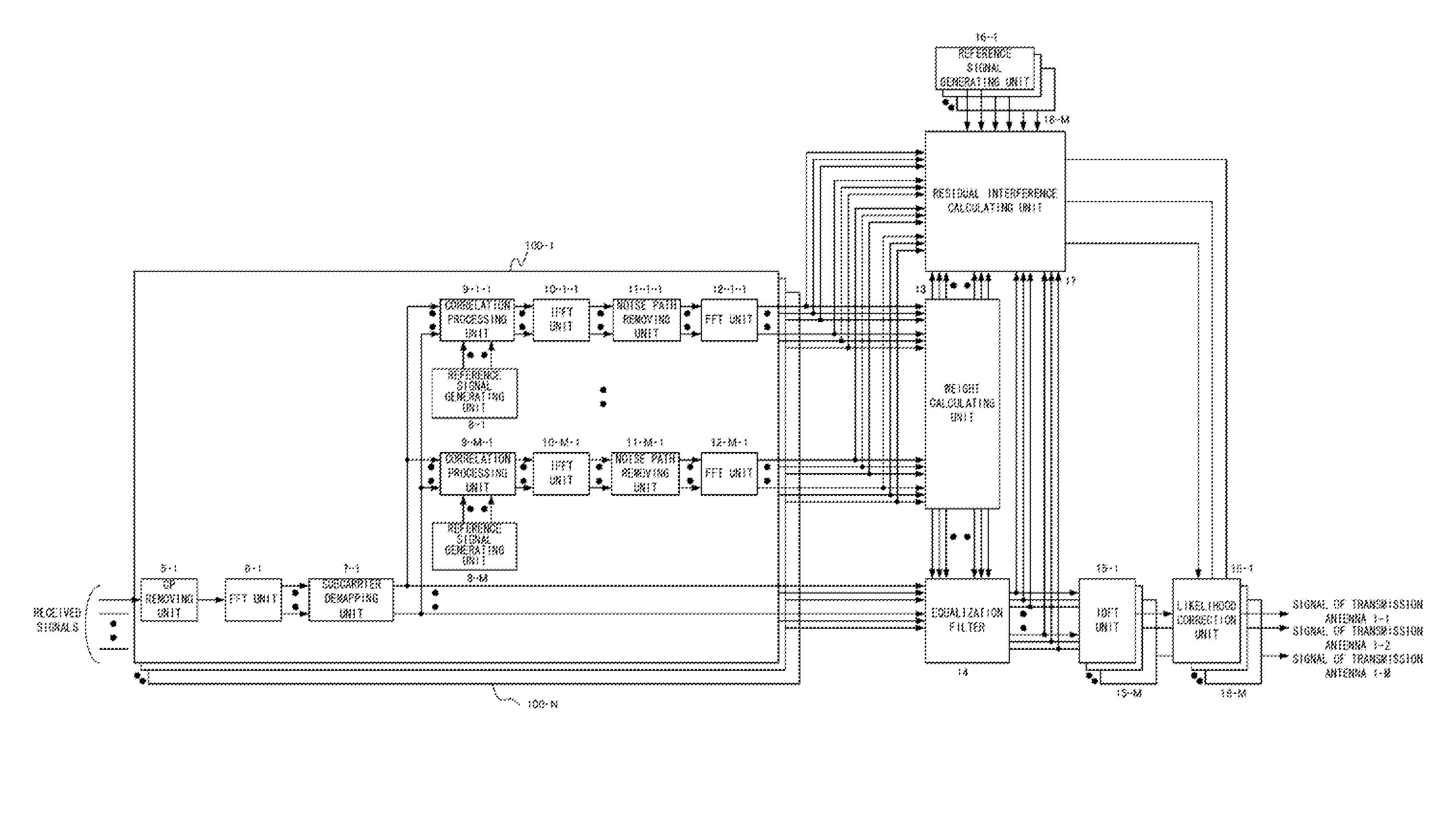
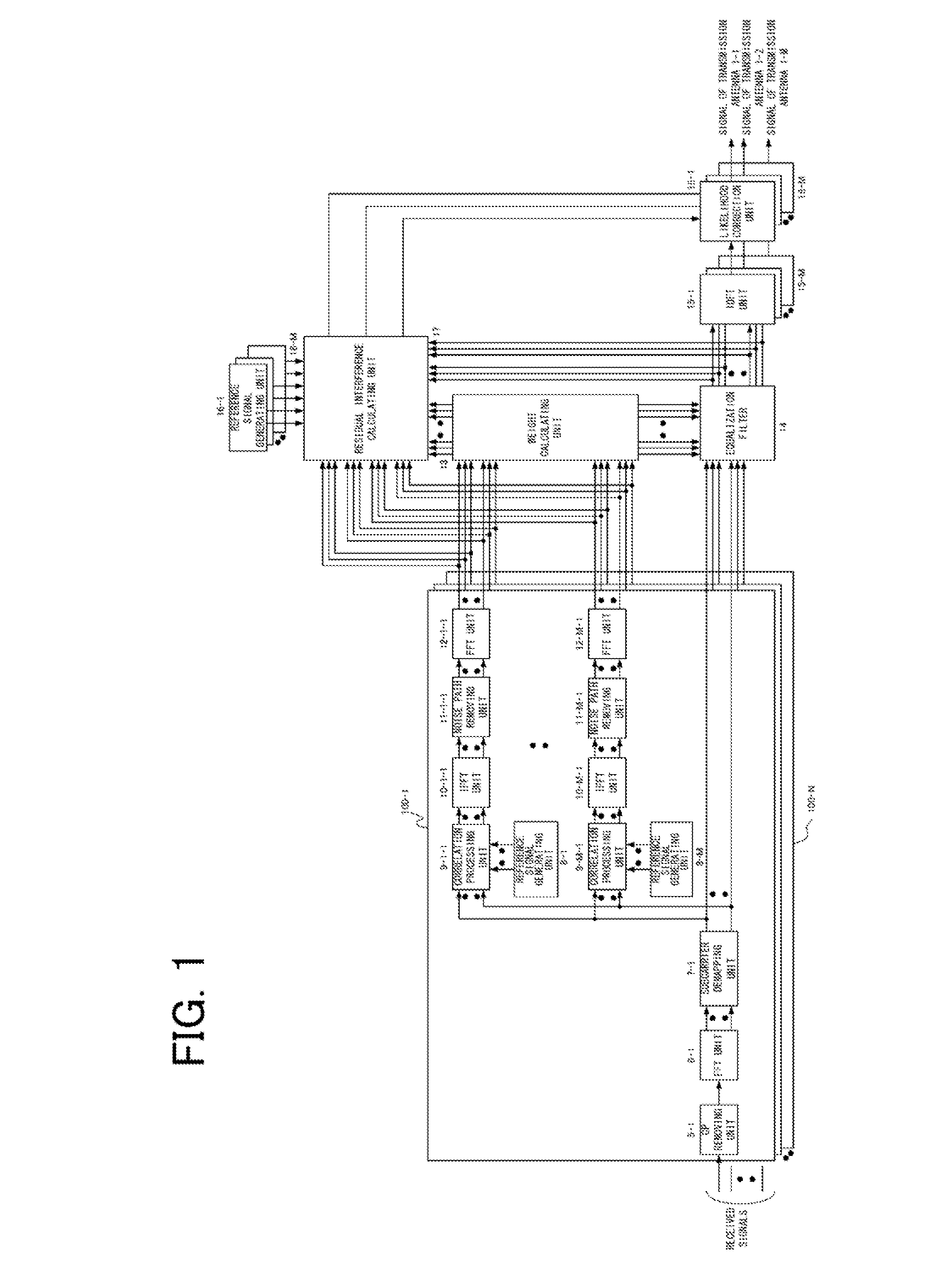
[0076]For further detailed description of the present invention, reference is made to the accompanying drawings. FIG. 1 is a block diagram showing a configuration of a MIMO receiving apparatus according to a first exemplary embodiment of the present invention.

[0077]Referring to FIG. 1, the MIMO receiving apparatus, with the number of the transmission antennas being M and that of the receive antennas being N, where M and N are each an integer greater than or equal to 1, is described.

[0078]Referring to FIG. 1, the MIMO receiving apparatus of the present exemplary embodiment includes:

[0079]CP removing units 5-1 to 5-N;

[0080]FFT units 6-1 to 6-N;

[0081]subcarrier demapping units 7-1 to 7-N;

[0082]reference signal generating units 8-1 to 8-M;

[0083]correlation processing units 9-1-1 to 9-M-N;

[0084]IFFT units 10-1-1 to 10-M-N;

[0085]noise path removing units 11-1-1 to 11-M-N;

[0086]FFT units 12-1-1 to 12-M-N;

[0087]a weight calculating unit 13;

[0088]an equalization filter 14;

[0089]IDFT units 15...


PUM


Abstract

Disclosed is a MIMO receiving apparatus in which a residual interference calculation unit (17) inputs noise-suppressed frequency domain channel estimation values, output from FFT units (12-1-1 to 12-M-N), equalizing weights calculated by a weight calculating unit (13), equalized signals from equalization processing by an equalization filter (14) and reference signals generated by reference signal generating units (16-1 to 16-M) to calculate a residual interference and the likelihood correction units (18-1 to 18-M) receive time domain equalized signal from the IDFT units (15-1 to 15-M) and the residual interference calculated by the residual interference calculation unit (17) to correct the likelihood of the equalized signal.

Description

[0001]This application is the National Phase of PCT / JP2009 / 054807, filed Mar. 12, 2009, which is based upon and claims the benefit of the priority of Japanese patent application No. 2008-064487, filed on Mar. 13, 2007, the disclosure of which is incorporated herein in its entirety by reference thereto.TECHNICAL FIELD[0002]This invention relates to a receiving apparatus and a receiving method. More particularly, it relates to a device and a method applied with advantage to a receiving apparatus of a MIMO system that transforms a plurality of single carrier signals received by a plurality of receive antennas into frequency domain signals to carry out signal demodulation by signal processing in the frequency domain.BACKGROUND ART[0003]In radio communication systems of next generation mobile communication, it is crucial to implement high speed data transmission. As a technique for implementing such high speed data transmission, a MIMO (Multiple Input Multiple Output) multiplexing system...

Claims


Application Information

Patent Timeline
Patent Type & Authority Applications(United States)
IPC IPC(8): H04L27/06
CPCH04B7/0413H04L2025/03426H04L25/03006H04B7/0854H04L25/03159H04L25/03891H04L25/067H04B7/08
Inventor KIMATA, MASAYUKI
Owner NEC CORP
Why Eureka
Try Eureka