Magazine quick-release blocking apparatus and method

Active Publication Date: 2011-01-20
QUIS TOMAS
29 Cites 21 Cited by

AI-Extracted Technical Summary

Problems solved by technology

However, certain laws (federal and state) prohibit the importation, sell, and/or use of such weapons in the United States unless certain modifications are made to the weapons.
However, laws are subject to change, and there has been a gro...

Benefits of technology

The previously summarized embodiments of the disclosure have been listed as examples only and are not meant to be limiting. These and other embodiments have many advantages, including prov...

Abstract

Apparatuses, methods, and kits are disclosed for preventing quick release of a magazine from a magazine well of a Sa vzor 58 rifle without the need to substantially disassemble the rifle, thereby providing a means to modify Sa vzor 58 rifles to bring such rifles within permissible limitations of certain local, state, and federal guns laws.

Application Domain

Technology Topic

Image

  • Magazine quick-release blocking apparatus and method
  • Magazine quick-release blocking apparatus and method
  • Magazine quick-release blocking apparatus and method

Examples

  • Experimental program(1)

Example

Various terms used herein are intended to have particular meanings. Some of these terms are defined below for the purpose of clarity. The definitions given below are meant to cover all forms of the words being defined (e.g., singular, plural, present tense, past tense). To the extent that any term below diverges from the commonly understood and/or dictionary definition of such term, the definitions below control.
Clipped Position: the position of a magazine relative to a rifle such that the magazine is secured to the rifle in a manner in which a round can be fired from the magazine (if at least one round is present in the magazine).
Magazine: a device for holding one or more rounds of ammunition and, in some cases, urging one or more rounds to a firing chamber of a rifle to which the magazine is attached in a clipped position.
Magazine Catch Pin: an elongated, preferably cylindrical, pin configured for extending through the width of a rifle along a passage to hold two or more objects together, preferably having a diameter or average cross-sectional distance ranging from about 3.8 mm to about 4.2 mm, and a length ranging from about 27 mm to about 31 mm.
Magazine Safety Pin: an elongated nail-like device preferably including a nail-like head and a bifurcated distal end defining a first leg and a second leg, wherein the second leg is preferably longer than the first leg and wherein the second leg preferably includes a ridge for holding the magazine safety pin in place after the magazine safety pin has been inserted into a magazine safety pin channel. The first leg preferably has a length ranging from about 24 mm to about 28 mm, and the second leg (including the ridge) preferably has a length ranging from about 26 mm to about 30 mm. The head preferably has a thickness of about 1 mm and a diameter or average cross-sectional length ranging from about 4 mm to about 6 mm.
Magazine Safety Pin Channel: An aperture along a ventral surface of a rifle where a magazine safety pin may be inserted so as to come into frictional contact with a magazine catch pin (if a magazine catch pin is present) whereby the magazine catch pin is substantially held in place by the magazine safety pin.
Magazine Well: a three-dimensional space defined at least in part by the contour of a receiver and including, for example, the space where a quick release mechanism is typically located.
Passage: a substantially linear channel, preferably cylindrical in shape, extending from an aperture located along a first side of an object to an aperture located along a second side of an object.
Receiver Cover: particularly with respect to a Sa vzor 58, a “receiver cover”50 is that portion or portions of a rifle that cover the receiver as shown, for example, in FIG. 18.
Substantially Disassembled: the state of a rifle—particularly a Sa vzor 58 rifle—in which the receiver cover has been removed. This is typically a necessary step in order to remove a magazine safety pin from a Sa vzor 58 rifle.
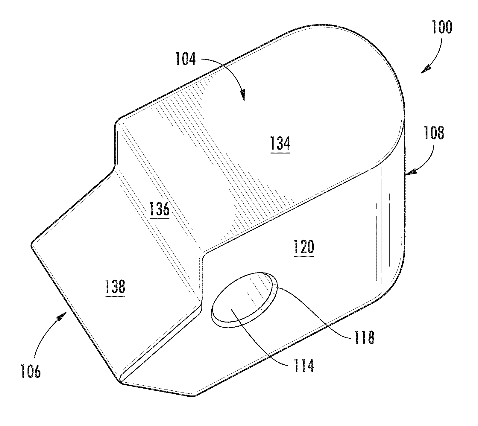
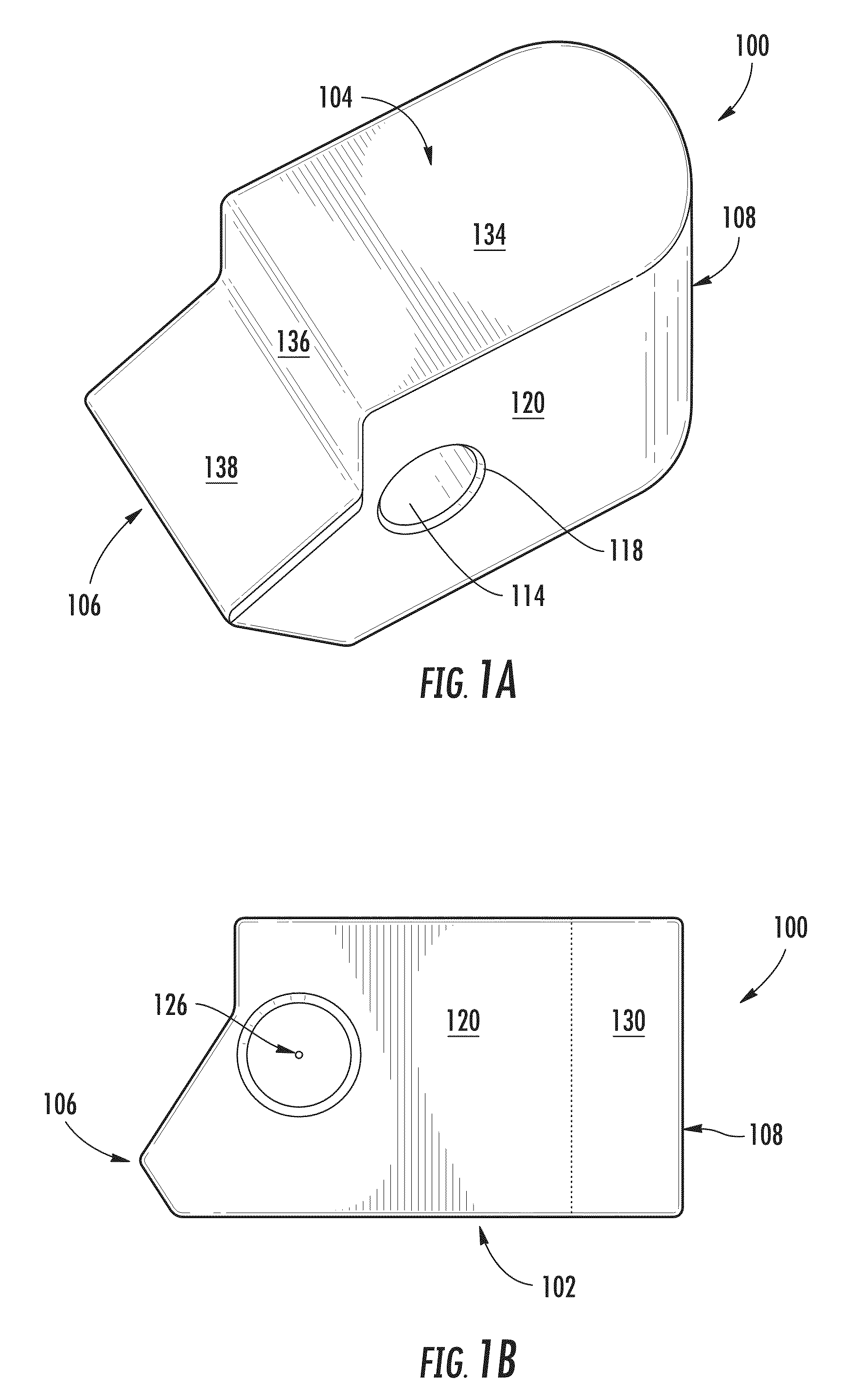
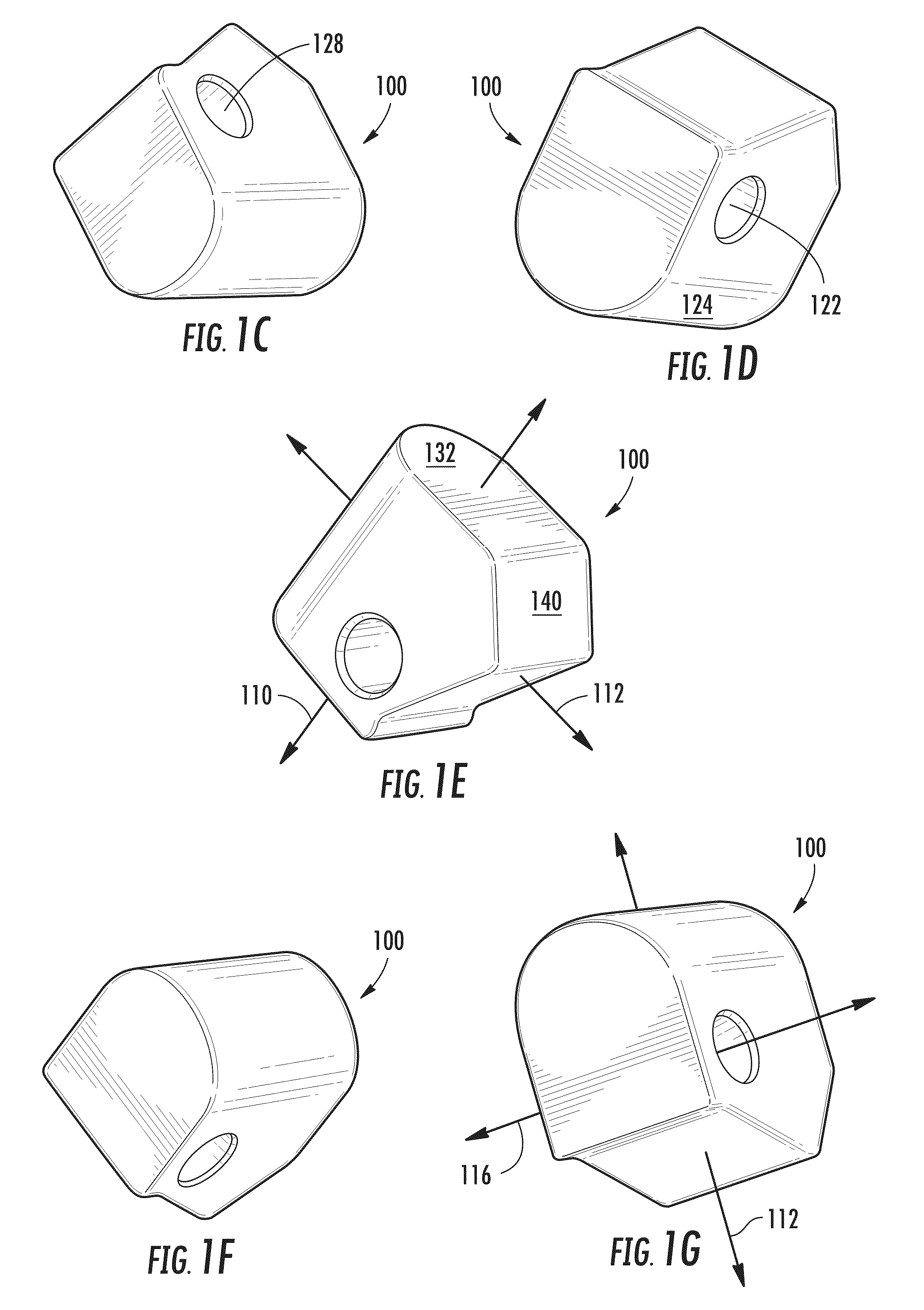
FIGS. 1A-1G show various views of an embodiment of the invention including a multifaceted rigid object 100. The object 100 or other embodiments thereof can be described by defining a distal end 102 and a proximal end 104 as well as an engagement end 106 and a back end 108. The distal end 102 end and the proximal end 104 together define a first axis 110 which is generally oriented in the dimension hereinafter referred to as “height” or the “height dimension.” The engagement end 106 and the back end 108 together define a second axis 112 which is generally oriented in the dimension hereinafter referred to as “length” or the “length dimension.” The first axis 110 is preferably substantially orthogonal to the second axis 112.
The object 100 further includes a passage 114 that extends through the dimension hereinafter referred to as “width” or the “width dimension” along a third axis 116. The passage 114 defines a first aperture 118 along a first side face 120 of the object 100 and a second aperture 122 along a second side face 124 of the object 100. The third axis 116 extends along an imaginary line passing through a first central point 126 of the first aperture 118 and a second central point 128 of the second aperture 122. Thus, in certain embodiments, the third axis could be referred to as a “central” axis because it runs in linear fashion between the first central point 126 and the second central point 128. In the embodiment shown in FIGS. 1A-1G, the first central point 126 and the second central point 128 are easily determined because the first aperture 118 and the second aperture 122 are each in the form of an orifice having a circular shape. The length of the diameters defining the first aperture 118 and the second aperture range from about 1.7 mm to about 2.4 mm, and most preferably about 2.1 mm. Although a circular shaped cross section through the passage 114 is preferred, other embodiments may include, for example, a passage including an irregular shaped cross section, a dynamically shaped cross section that differs along the third axis, or a regular shaped cross section in the shape of a polygon or non-circular curved shape.
The embodiment shown in FIGS. 1A-1G includes a specific arrangement of faces including the first side face 120 and the second side face 124 as well as an end face 130, a distal face 132, a proximal face 134, a first engagement face 136, a second engagement face 138, and a third engagement face 140. FIG. 2 shows preferred dimensions for the embodiment shown in FIG. 1 and shows that the end face 130 is preferably a curved surface that extends around at approximately 180 degrees. The dimensions shown in FIG. 2 are given in millimeters (mm) with preferred tolerance ranges of +/−0.1 mm. However, less precise versions of the embodiment shown in FIGS. 1-2 are contemplated viable and useful by Applicant.
Generally, the preferred maximum length of the object 100 ranges from about 11.5 mm to about 12.0 mm. The preferred maximum width of the object 100 ranges from about 10.5 mm to about 11.0 mm. The preferred maximum height of the object 100 preferably ranges from about 13.8 mm to about 14.2 mm so that the proximal face 134 is substantially flush with the surrounding surface of a rifle to which the object 100 may be attached as shown, for example, in FIG. 3. However, the distance between the proximal end 104 and the distal end 102 may be greater than 14.2 mm (e.g., ranging from about 14.2 mm to about 25 mm or more) such that the proximal end 104′ of a related embodiment object 100′ extends beyond the surrounding surface of a rifle to which the object 100′ is attached as shown in FIG. 4A. FIGS. 4B-4J show examples of some other potential embodiments with various faces and surface orientations, but having the same structural characteristics as defined above with respect to the first axis 110, the second axis 112, and the third axis 116. FIGS. 4A-4J show a small sampling of the various shapes that are contemplated by this disclosure.
With reference back to the embodiment shown in FIGS. 1A-1G, the third axis 116 is preferably located a shortest distance from the distal end 102 of the object 100 of from about 9.7 mm to about 10.1 mm, and most preferably about 9.9 mm. The third axis 116 is also preferably located a shortest distance from the back end 108 of the object 100 of from about 8.5 mm to about 8.9 mm, and most preferably about 8.7 mm.
Another embodiment of the invention is shown in FIG. 5 including a first version of a Sa vzor 58 rifle 200 including the object 100 (or variation thereof) described above. The rifle 200 also includes a magazine well 202, a magazine 204 oriented in a clipped position with the magazine well 202, and a magazine catch pin 206. The magazine well 202 further includes a groove 208 where a spring-loaded magazine quick release lever (shown in FIG. 6) is typically located, but where the object 100 is located to prevent quick release of the magazine 204 without substantial disassembly of the rifle 200. The object 100 is located in the groove 208 such that the distal end 102 of the object 100 is oriented toward (i.e., “substantially facing”) the rifling chamber of the rifle, the proximal end 104 of the object 100 is oriented away from the rifling chamber, the engagement end 106 of the object 100 is oriented toward the magazine 204, and the back end 108 of the object 100 is oriented toward a triggering mechanism.
The rifle 200 also preferably includes a magazine safety pin 210 which, in typical Sa vzor 58 rifles, functions (at least in part) to maintain the magazine catch pin 206 in place so that, among other things, the magazine 204 does not detach during firing of the rifle 200. The object 100, the magazine catch pin 206, and the magazine safety pin 210 are shown in disassembled form in FIGS. 7A-7C. When the rifle 200 is substantially fully assembled, the magazine catch pin 206 is located through a first catch pin aperture 216, into the passage 114 of the object 100, and over to a second catch pin aperture 218 such that the passage 114 is substantially aligned with the first rifle catch pin aperture 216 and the second catch pin aperture 218. FIG. 8 shows the magazine catch pin 206 being inserted through the first rifle catch pin aperture 216 and into the passage 114.
In similar fashion (but in a different spatial orientation), the magazine safety pin 210 is located at least partially in a magazine safety pin channel 220 oriented substantially orthogonal to the catch pin 206 helping to hold the catch pin 206 in a relatively stationary position, thereby ensuring that the object 100 remains in place which further guarantees that the magazine 204 remains in a clipped position. FIG. 9 shows the magazine safety pin 210 being inserted into the magazine safety pin channel 220.
In the embodiment shown in FIG. 5, the magazine 204 is configured for holding no more than ten rounds of ammunition. In another embodiment, for example, a magazine may be used that is configured for holding about thirty rounds of ammunition. The capacity of the magazine used is not necessarily relevant so long as such magazine is configured to be in a clipped position with the rifle 200.
In a related embodiment shown in FIG. 10, a magazine 300 is contemplated wherein the magazine 300 further includes the object 100 (or variation thereof) permanently attached as a part of the magazine 300 by, for example, welding. The magazine 300 is configured to be in a clipped position with a Sa vzor 58 rifle including the groove 208 described above. The magazine 300 is preferably further configured such that the first aperture 118 and the second aperture 122 of the object 100 substantially align with first magazine catch pin aperture 216 and the second magazine catch pin aperture 218, respectively, of an Sa vzor 58 rifle so that the magazine 300 may be held in place with no quick release capability by the magazine catch pin 206 and the magazine safety pin 210.
In yet another embodiment shown in FIG. 11, a second version of a Sa vzor rifle 400 includes the object 100 (or variation thereof) described above. The rifle 400 also includes the magazine well 202 and the magazine 204 oriented in a clipped position with the magazine well 202. The magazine well 202 further includes the groove 208 where a spring-loaded magazine quick release lever (shown in FIG. 6) is typically located, but where the object 100 has been attached to prevent release of the magazine 204. In this embodiment, the object 100 is permanently attached to the groove 208 by, for example, welding after the magazine 204 has been oriented in a clipped position. This way, the magazine 204 may not be removed. Therefore, in this particular embodiment, the rifle 400 must be rifle loaded from the top of the rifle 400. In a related embodiment, a modified version of the object 100 is used wherein there is no passage 114. The passage 114 is preferred, however, because the placement of the magazine catch pin 206 through the first rifle catch pin aperture 216, through the passage 114 of the object 100, and through the second catch pin aperture 218 helps to properly position the object 100 prior to welding the object 100 with the surrounding groove 208 surfaces.
FIGS. 7A-7C shows embodiments of a kit 500 of parts for use to modify a Sa vzor 58 rifle. The kit 500 includes the object 100 (or variation thereof). In a preferred embodiment, the kit 500 further includes the magazine catch pin 206 and the magazine safety pin 210. Typically, a rifle being modified already has a magazine catch pin and a magazine safety pin. However, such parts may be worn or otherwise damaged, so the preferred embodiment of the kit 500 provides extra parts.
The object 100 is preferably made of metals or metal alloys such as, for example, steel, stainless steel, aluminum, titanium, iron, cobalt, nickel, copper, zinc, and mixed alloys thereof. The magazine catch pin 206 and the magazine safety pin 210 are also preferably made of the same material(s).
In addition to the various embodiments of apparatuses and kit disclosed above, methods for assembling a modified Sa vzor 58 so that a magazine placed in a clipped position relative to the rifle cannot be detached from the rifle rapidly or, in some cases, at all are disclosed. One embodiment includes the steps of (A) providing an Sa vzor 58 rifle (200, 400) including a magazine well 202 and a groove 208 as described above as shown in FIGS. 12-13; (B) placing the magazine 204 in a clipped position as shown in FIGS. 14-15; (C) inserting the object 100 (or variation thereof) into the groove 208 leading with the distal end 102 of the object 100 such that the engagement end 106 of the object 100 is facing the magazine 204; (D) placing the magazine catch pin 206 through the first rifle catch pin aperture 216, into the passage 114 of the object 100, and over to the second catch pin aperture 218 as shown in FIG. 8; and (E) forcing the magazine safety pin 210 into the magazine safety pin channel 220 as shown in FIG. 9. A rifle assembled using the steps described above is shown, for example, in FIGS. 16-17.
In one embodiment, step (A) above further includes the sub-steps of (i) removing the magazine 204 from an Sa vzor 58 rifle 700 as shown in FIGS. 18-20, wherein the rifle 700 is equipped with a quick release mechanism 702 including a lever 704 and a spring 706 (FIG. 21), leaving the rifle 700 with no magazine as shown in FIG. 22; (ii) forcing the magazine safety pin 210 out of the magazine safety pin channel 220 as shown in FIG. 23; (iii) removing the magazine catch pin 206 as shown in FIG. 24; and (iv) removing the quick release mechanism 702 so that an Sa vzor 58 rifle having no attached quick release mechanism is provided prior to step (B).
Another embodiment of a method is disclosed including the steps of (A) providing an Sa vzor 58 rifle (200, 400) including a magazine well 202 including a groove 208 as described above and as shown in FIGS. 13-14; (B) placing the magazine 204 in a clipped position as shown in FIGS. 15-16; (C) inserting the object 100 (or variation thereof including, for example, a version having no passage 114) into the groove 208 leading with the distal end 102 of the object 100 such that the engagement end 106 of the object 100 is facing the magazine 204; and (F) welding the object 100 to one or more of the groove 208 surface(s).
Various embodiments described herein are used to effectively disable/modify the magazine quick release feature of Sa vzor 58 rifles so that such rifles may comply with various national and state laws in the United States.
The previously described embodiments of the present disclosure have many advantages, including providing a relatively inexpensive kit and/or apparatus and relatively simple methods to modify Sa vzor rifles. With regards to certain embodiments described above, in order for the magazine safety pin 210 to be removed, it is necessary for the receiver cover to be removed so that a distal end of the magazine safety pin 222 may be hammered or otherwise manipulated so as to force the magazine safety pin 210 out of the magazine safety pin channel 220. Thus, the magazine 204, when in a clipped position, cannot be removed unless the rifle is substantially disassembled. With regards to the embodiments disclosed wherein the object 100 (or variation thereof) is permanently attached (e.g., welded) to one or more of the groove 208 surface(s), the magazine 204 cannot be removed at all without causing undesirable damage to the rifle. Many current technologies allow a user to use a hand tool to disengage a magazine from a rifle, but these technologies are at the very edge of the law in some jurisdictions and may be nonviable as gun laws fluctuate throughout the United States. Thus, the apparatuses, kits, and methods described herein provide a conservative and viable option to modify Sa vzor 58 rifles or otherwise use a modified Sa vzor 58 rifle with confidence that such use is within the limits of most if not all applicable gun laws in the United States related to firearms.
The foregoing description of preferred embodiments of the present disclosure has been presented for purposes of illustration and description. The described preferred embodiments are not intended to be exhaustive or to limit the scope of the disclosure to the precise form(s) disclosed. Obvious modifications or variations are possible in light of the above teachings. The embodiments are chosen and described in an effort to provide the best illustrations of the principles of the disclosure and its practical application, and to thereby enable one of ordinary skill in the art to utilize the concepts revealed in the disclosure in various embodiments and with various modifications as are suited to the particular use contemplated. All such modifications and variations are within the scope of the disclosure as determined by the appended claims when interpreted in accordance with the breadth to which they are fairly, legally, and equitably entitled.
Any element in a claim that does not explicitly state “means for” performing a specified function, or “step for” performing a specific function, is not to be interpreted as a “means” or “step” clause as specified in 35 U.S.C. §112, ¶ 6. In particular, the use of “step of” in the claims herein is not intended to invoke the provisions of 35 U.S.C. §112, ¶6.

PUM

PropertyMeasurementUnit
Length0.0115m
Length0.012m
Length0.0105m
tensileMPa
Particle sizePa
strength10

Description & Claims & Application Information

We can also present the details of the Description, Claims and Application information to help users get a comprehensive understanding of the technical details of the patent, such as background art, summary of invention, brief description of drawings, description of embodiments, and other original content. On the other hand, users can also determine the specific scope of protection of the technology through the list of claims; as well as understand the changes in the life cycle of the technology with the presentation of the patent timeline. Login to view more.

Similar technology patents

Customized financial transaction pricing

ActiveUS20100114713A1Accurate and efficient calculationSimple methodComplete banking machinesFinanceProduct dataPayment processor
Owner:AMERICAN EXPRESS TRAVEL RELATED SERVICES CO INC

Aluminum-silicon alloy refining agent and preparation thereof

Owner:营口经济技术开发区金达合金铸造有限公司

Classification and recommendation of technical efficacy words

Why Eureka
Try Eureka