Riser technology

a technology of rudder and rudder body, which is applied in the direction of passenger handling apparatus, special purpose vessels, borehole/well accessories, etc., can solve the problems of large, high cost, and often inability to economically justify the use of multiple purposes of the same vessel

Inactive Publication Date: 2011-01-20
MY TECH L LC
View PDF42 Cites 41 Cited by
  • Summary
  • Abstract
  • Description
  • Claims
  • Application Information

AI Technical Summary

Benefits of technology

[0013]SSR designed for low cost fabrication, and installation, relocation and recovery by a small vessel

Problems solved by technology

A MODU is a large, high cost, multipurpose vessel which frequently can not be economically justified, given the limited additional product that can be recovered from a partially depleted reservoir.

Method used


Image

  • Riser technology
  • Riser technology
  • Riser technology

Examples


Embodiment Construction

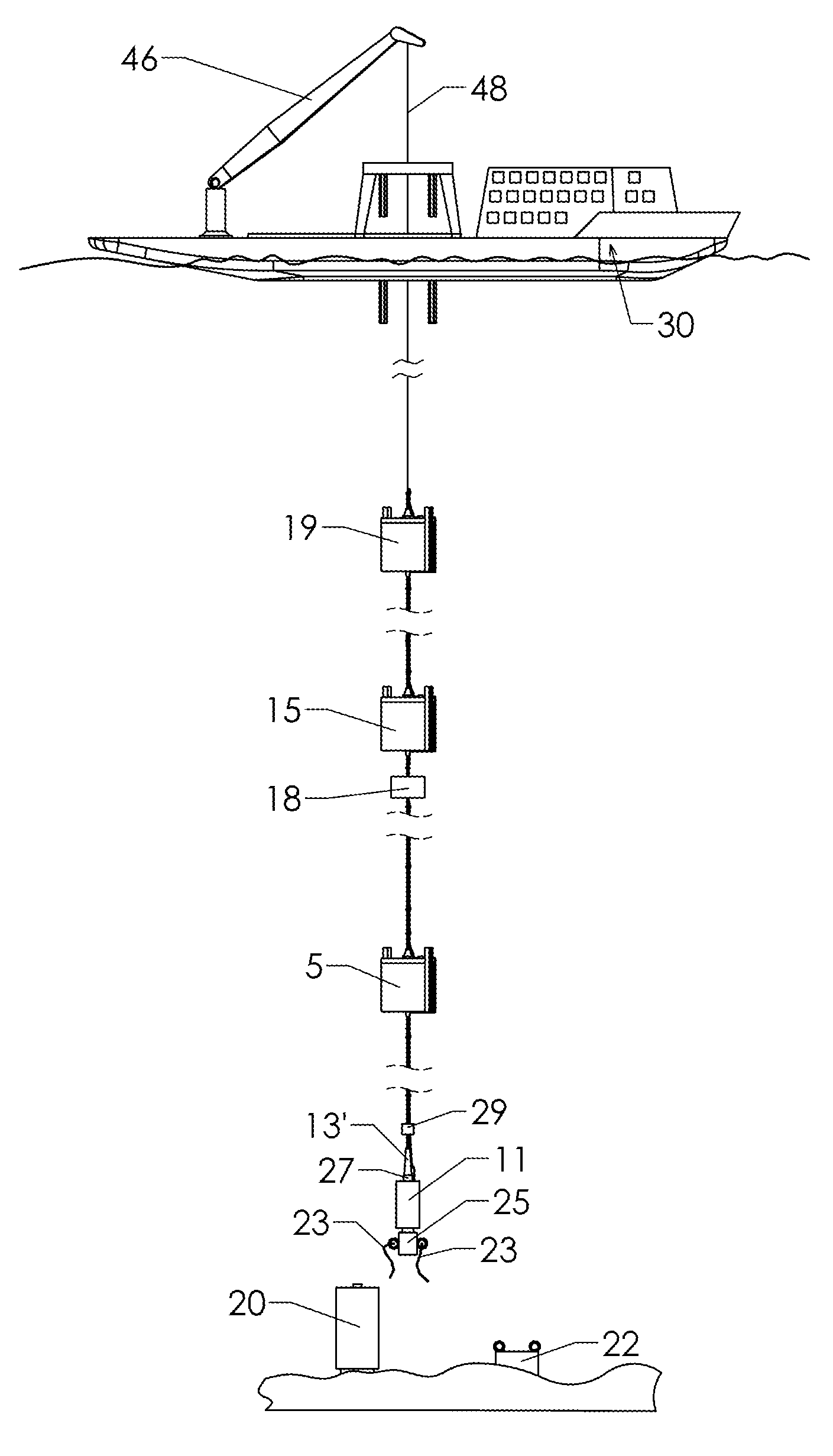
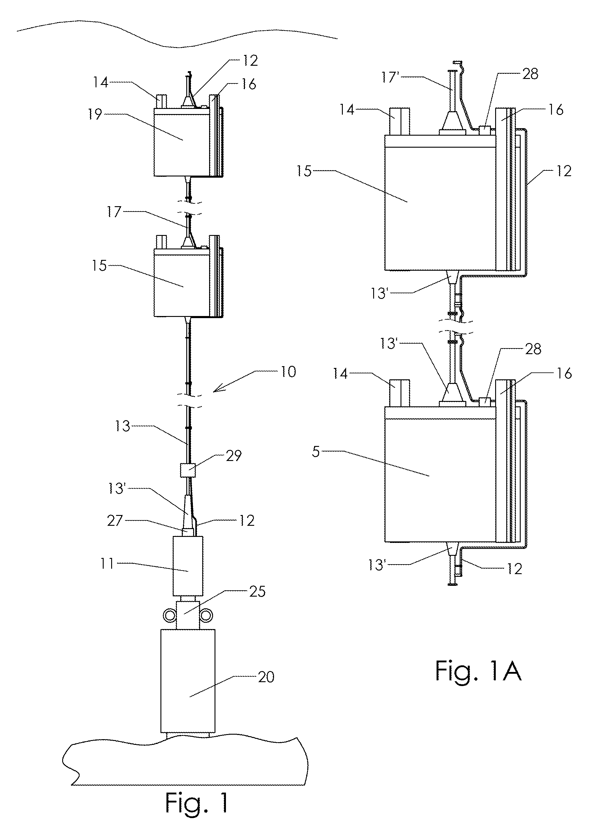
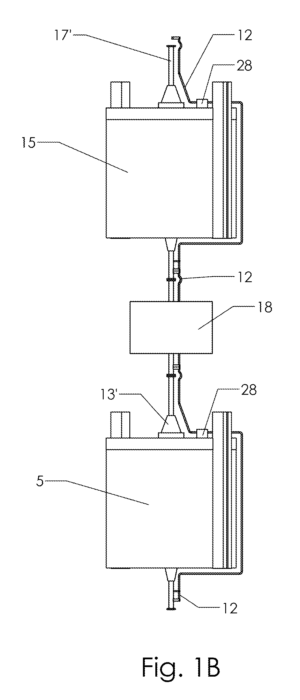
[0057]A Self-Supporting Riser (SSR) of the present invention is readily configured to provide downhole intervention in a well. The vessels used for installation or recovery and intervention are small vessels.

[0058]The subsea wells of specific interest for the present invention are those that have been drilled off-shore in water depths of approximately 500 to 10,000 feet and are not located under a host facility. Thus, the SSR of the present invention is a substantial structure. The SSR extends up from the seafloor with the top of the SSR near but below the water surface and typically below the wave zone and ship traffic. The modular components of the present invention can be assembled into unique SSR configurations and installed to meet the requirements of depth, parameters such as current found at the location and specific application needs, and to fit a particular existing well head or tree. The hydrocarbon production equipment to which the SSR is connected may be sea floor archit...


PUM

PropertyMeasurementUnit
depthsaaaaaaaaaa
internal diameteraaaaaaaaaa
pressureaaaaaaaaaa

Abstract

The present invention is directed to novel methods and apparatus for the design, installation, use, recovery, and reuse of a Self Supporting Riser (SSR) for wells that are not under a platform. The SSR of the present invention uses standardized joints that can be recovered, potentially warehoused, and recombined in different configurations for different purposes or locations. Emphasis is on methods and apparatus that use relatively small vessels subject to high motions in the installation, use and recovery of the SSR. The SSR is adapted for high current and / or deep water applications for purposes of downhole well intervention and subsea equipment installation. In contrast to the apparatus and processes of the prior art, this invention addresses a comprehensive system design.

Description

CROSS-REFERENCE TO RELATED APPLICATIONS[0001]This application claims benefit of U.S. provisional application Ser. Nos. 61 / 225,601, filed Jul. 15, 2009; 61 / 232,551, filed Aug. 10, 2009; 61 / 252,815, filed Oct. 19, 2009; 61 / 253,230, filed Oct. 20, 2009; 61 / 253,200, filed Oct. 20, 2009, all of which are incorporated herein by reference.STATEMENT REGARDING FEDERALLY SPONSORED RESEARCH OR DEVELOPMENT[0002]Not Applicable.FIELD OF INVENTION[0003]The present invention is directed to a practical, low cost modular, reusable tubular / Self Supporting Riser (SSR) and provisions for interfacing a vessel subject to high motions to the SSR. The SSR can be easily installed and recovered in a wide range of water depths and in areas of high current. The installed SSR can be left untended. Moreover, the SSR can be configured for workover of a well through the SSR using coiled tubing, joints of drill pipe, or wire line equipment and fluids from wells drilled to fossil hydrocarbon reservoirs deep below the...

Claims


Application Information

Patent Timeline
Patent Type & Authority Applications(United States)
IPC IPC(8): B63B35/00E21B17/01B63B39/00B63B27/10B23P11/00
CPCB63B35/44B66C13/02E21B19/002Y10T29/49826E21B19/006E21B19/22E21B19/004B63B2003/147
Inventor YEMINGTON, CHARLES R.
Owner MY TECH L LC
Why Eureka
Try Eureka