Power tool

Inactive Publication Date: 2011-01-20
ROBERT BOSCH GMBH
View PDF28 Cites 54 Cited by
  • Summary
  • Abstract
  • Description
  • Claims
  • Application Information

AI Technical Summary

Problems solved by technology

In power tools, particularly in hand-guided drills and rotary hammers, vibrations are generated, in particular by an impact mechanism, which cause a user to tire more quickly and reduce the grasping force that the user is able to exert.
A vibration damping achieved in this way is often insufficient.
In power tools with a pistol-grip design, it is particularly problematic to achieve a vibration damping because devices of this kind have a compact d

Method used


Image

  • Power tool
  • Power tool
  • Power tool

Examples


Embodiment Construction

[0019]The same elements are provided with the same reference numerals in all of the drawings.

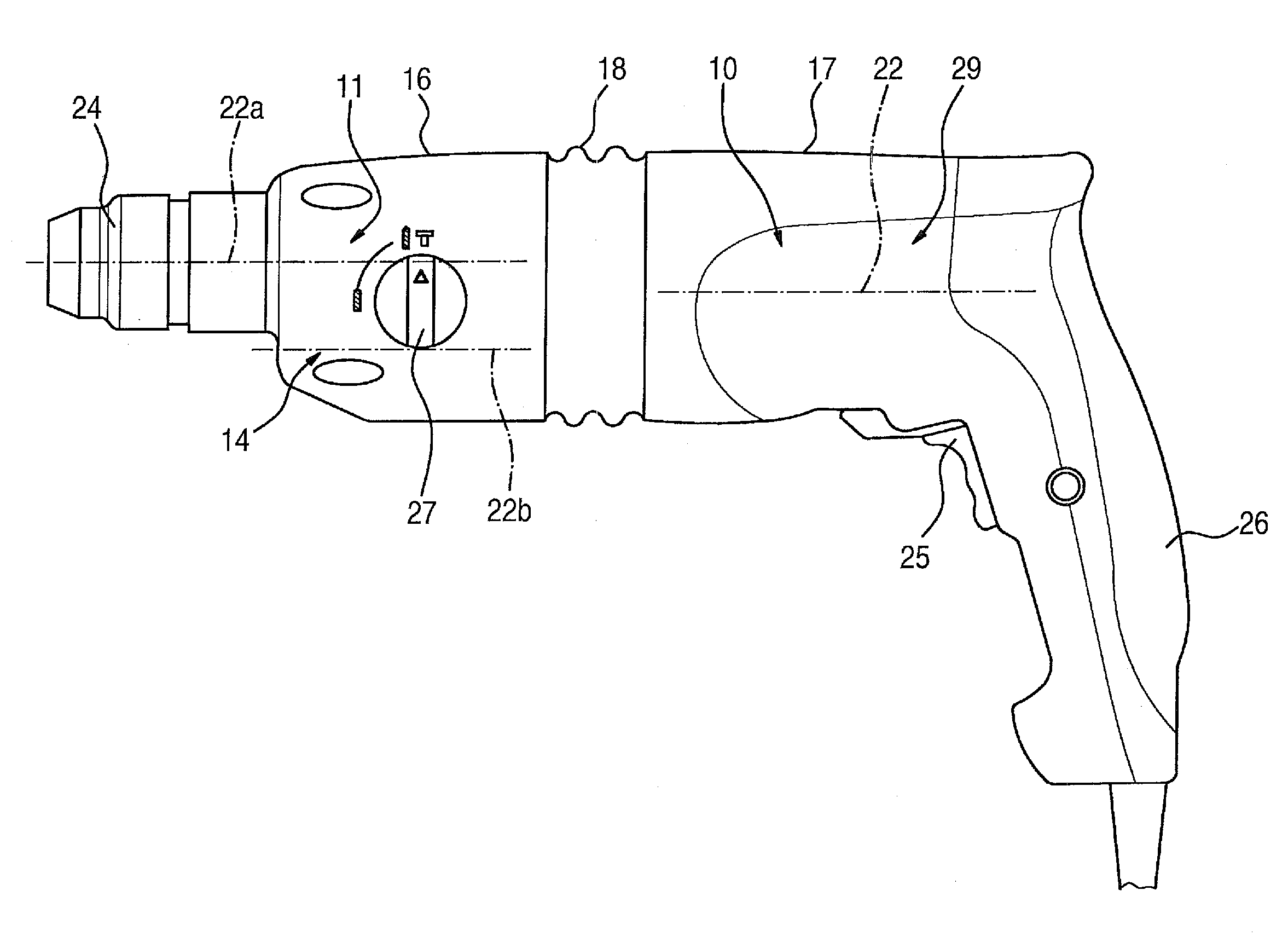
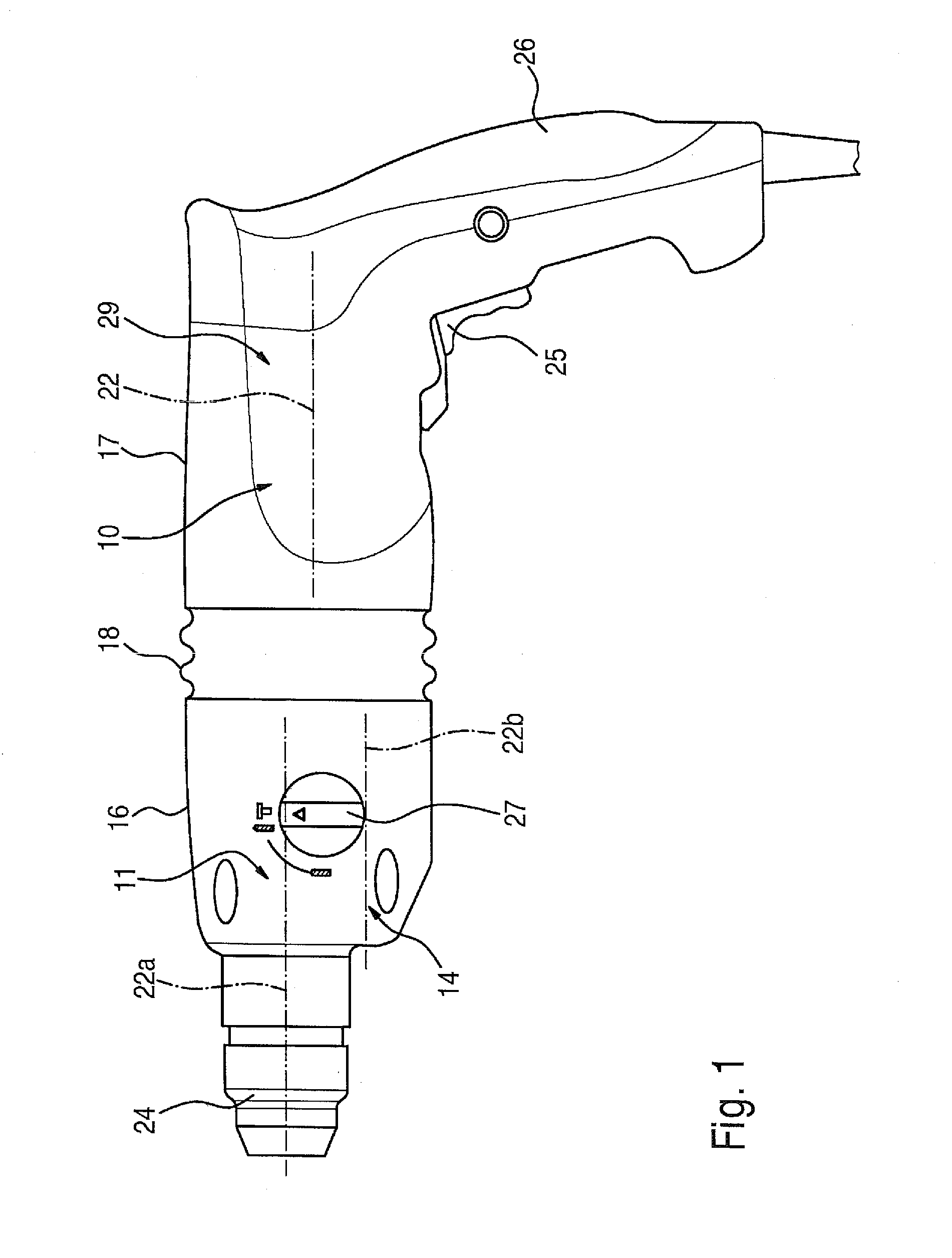
[0020]FIG. 1 shows a hand-guided power tool of a pistol-grip design with a grip 26. The power tool usually includes various functional units such as a drive unit 10, e.g. an electric motor, a transmission unit 11, and a unit for securing and supporting a spline shaft 14, which is connected in a force-transmitting fashion to a tool holder embodied in the form of a spindle 24 for accommodating an insert tool that is not visible in FIG. 1. The insert tool, for example a screwdriving bit or drill bit, can be driven in a rotating and / or hammering fashion. The above-mentioned functional units in the pistol-grip design shown here are arranged axially one after another and are coupled to one another by means of frictional and / or form-locking engagement. In this case, a drive axis 22 of an armature shaft 29, an axis 22b of the spline shaft 14, and an axis 22a of a spindle 24 are axially parallel to o...


PUM


Abstract

The invention relates to an electric machine tool, in particular, having the construction of a pistol, comprising a drive unit (10) and a transmission unit (11). At least the drive unit (10) is mounted on an intermediate flange and is provided with a toothed shaft (14) in order to drive a drive train. According to the invention, the intermediate flange is distributed on the drive side and the transmission side of the bearing bridge element (12, 13), which are connected together via a vibration dampening device (15).

Description

PRIOR ART [0001]The invention is based on a power tool as recited in the preamble to claim 1.[0002]In power tools, particularly in hand-guided drills and rotary hammers, vibrations are generated, in particular by an impact mechanism, which cause a user to tire more quickly and reduce the grasping force that the user is able to exert. Oscillations that are transmitted from a machining point via the machining tool can amplify such vibrations. It is known to reduce such vibrations and oscillations, for example by providing grips that are partially covered with rubber. A vibration damping achieved in this way is often insufficient.[0003]In power tools with a pistol-grip design, it is particularly problematic to achieve a vibration damping because devices of this kind have a compact design in which a drive axis is oriented axially parallel to an axis of a spindle and of one or more intermediate shafts. Percussion drills and rotary hammers, for example, have such a design. These machines ...

Claims


Application Information

Patent Timeline
IPC IPC(8): B25D17/24B25F5/02
CPCB25D11/062B25D17/24B25F5/006B25D2250/121B25D2250/371B25D2211/061
Inventor SAUR, DIETMAR
Owner ROBERT BOSCH GMBH
Why Eureka
Try Eureka