Shielding tape with multiple foil layers

a shielding tape and foil layer technology, applied in the direction of insulated conductors, power cables, cables, etc., can solve the problems of affecting the attachment of the connector to the cable, the shielding structure may also separate, and the cost and complexity of cabling production, so as to reduce the egress or ingress of signals, improve the flex life of the shield tape, and save costs

Active Publication Date: 2011-01-20
PCT INT
View PDF100 Cites 38 Cited by
  • Summary
  • Abstract
  • Description
  • Claims
  • Application Information

AI Technical Summary

Benefits of technology

[0006]A coaxial cable of the present invention comprises a center conductor, a dielectric surrounding the center conductor, a shielding tape surrounding the dielectric, a braided metal surrounding the shielding tape, and an outer jacket surrounding the braided metal. The shielding tape comprises: (i) a first shielding layer bonded to a first separating layer; (ii) a second shielding layer bonded to the first separating layer and a second separating layer; and (iii) a third shielding layer bonded to the second separating layer. The present invention eliminates the potential problem of the outer shielding structures separating and interfering with connector attachment. Furthermore, the use of three or more shielding layers in the shielding tape of the present invention improves the flex life of the shield tape by covering micro-cracks in the metal layers with additional shielding layers, thus reducing signal egress or ingress. Accordingly, the present invention provides cost savings and / or an improvement in shielding performance.

Problems solved by technology

Multiple layers of shielding tape, while providing better shielding performance, also add to the cost and complexity of producing the cabling.
Conventional shielding tape, with only one or two shielding layers, is susceptible to allowing RF signal egress or ingress as micro-cracks form in the shielding layers and align with each other as a result of flexing the cable.
These outer shielding structures may also separate and interfere with the attachment of a connector to the cable.

Method used


Image

  • Shielding tape with multiple foil layers
  • Shielding tape with multiple foil layers
  • Shielding tape with multiple foil layers

Examples


Embodiment Construction

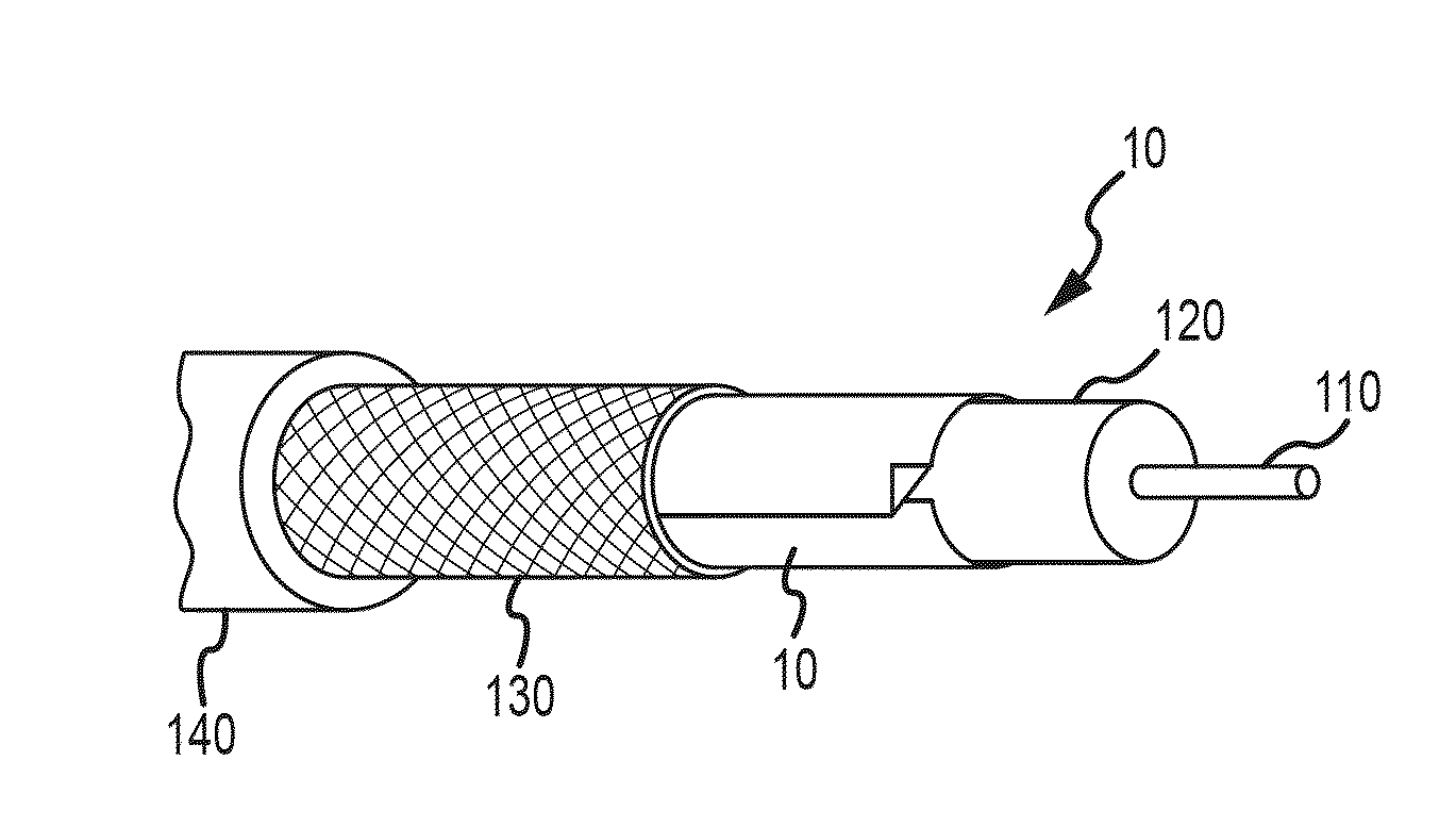
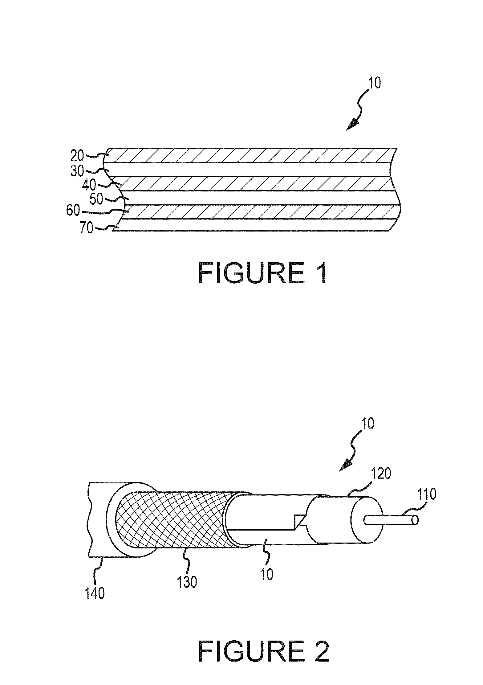
[0013]Turning now to the drawings, where the purpose is to describe preferred embodiments of the invention and not limit same, FIG. 1 shows a shielding tape 10.

[0014]Shielding tape 10 according to the present invention comprises at least three layers of shielding material (which are also called “shielding layers”). As shown in FIG. 1, the shielding tape 10 comprises a laminate structure of aluminum 20 / PET 30 / aluminum 40 / PET 50 / aluminum 60, with a hot melt adhesive 70 (which is preferably EAA or EMAA) applied to aluminum layer 60.

[0015]The aluminum layers of the exemplary shielding tape 10 are each about 9 microns thick, while the separating layers are about 12 microns thick. There is also a layer of adhesive between each aluminum / PET layer of about 2 microns thick. The adhesive layer 70 is about 25 microns thick. Other embodiments of the present invention may include shielding layers of at least 3 microns thick, separating layers of at least 4 microns thick, and adhesive layers of a...


PUM

PropertyMeasurementUnit
thickaaaaaaaaaa
thickaaaaaaaaaa
thickaaaaaaaaaa

Abstract

A coaxial cable of the present invention comprises a center conductor, a dielectric surrounding the center conductor, a shielding tape surrounding the dielectric, a braided metal surrounding the shielding tape, and an outer jacket surrounding the braided metal. The shielding tape comprises: (i) a first shielding layer bonded to a first separating layer; (ii) a second shielding layer bonded to the first separating layer and a second separating layer; and (iii) a third shielding layer bonded to the second separating layer. The present invention eliminates the potential problem of the outer shielding structures separating and interfering with connector attachment. Furthermore, the use of three or more shielding layers in the shielding tape of the present invention improves the flex life of the shield tape by covering micro-cracks in the metal layers with additional shielding layers, thus reducing signal egress or ingress. Accordingly, the present invention provides cost savings and/or an improvement in shielding performance.

Description

CROSS REFERENCE TO RELATED APPLICATIONS[0001]This nonprovisional utility application claims priority to U.S. Provisional Patent Application No. 61 / 226,250, filed Jul. 16, 2009 titled “Shielding Tape With Multiple Foil Layers,” the disclosure of which is fully incorporated herein by reference for all purposes.BACKGROUND[0002]Shielding is used in a variety of cables to reduce electrical interference that could affect a signal travelling through the cable. The shielding also helps to prevent the signal from radiating from the cable and interfering with other devices. One such type of shielding includes either one or two layers of aluminum or other shielding material (such as silver, copper, or Mu-metal) wherein each shielding layer is laminated onto (and if there is more than one shielding layer, each shielding layer is separated by) a separating layer, such as a plastic, e.g., polyethylene terephthalate (“PET”) or a polyolefin such as polypropylene (“PP”). This type of shielding that ...

Claims


Application Information

Patent Timeline
Patent Type & Authority Applications(United States)
IPC IPC(8): H05K9/00H01B9/02
CPCH01B11/1008H01B11/1016H05K9/0098H01B11/1826H01B11/1813Y10T29/49123
Inventor VISSER, LEONARD
Owner PCT INT
Why Eureka
Try Eureka