Feed device with improved grip

a feed device and grip technology, applied in the field of automatic feed modules or feeders, can solve the problems of reducing the effectiveness with which a single mailpiece is selected, and affecting the selection efficiency of mailpieces. , to achieve the effect of facilitating the subsequent selection of said mailpieces and reducing the drawbacks of mailpiece bunching

Active Publication Date: 2011-01-20
NEOPOST TECH SA
View PDF16 Cites 4 Cited by
  • Summary
  • Abstract
  • Description
  • Claims
  • Application Information

AI Technical Summary

Benefits of technology

[0005]An object of the present invention is to mitigate the drawbacks resulting from mailpiece bunching by proposing a franking machine feeder that makes it possible for the mailpieces to be presented in a novel manner to the guide, namely staggered relative thereto in a backwardly leaning stack, so as to facilitate subsequent selection of said mailpieces.
[0007]By means of this specific structure of the longitudinal referencing wall, bunching is systematically avoided and, by putting the first mailpieces in the stack into a staggered configuration in which the stack leans backwards, the work for selecting the mailpieces one-by-one is greatly facilitated. In addition, the quality of selection is improved when selecting fine envelopes.

Problems solved by technology

Such bunching is highly detrimental because it gives rise both to over-invoicing of one of the mailpieces (two mailpieces are weighed instead of a single mailpiece), and also to the underlying mailpiece not being franked and to the overlying mailpiece not being closed.
Unfortunately, since the guide is pressed against the mailpiece by a compression spring so as to prevent such bunching, mailpieces of large thickness, and more particularly such mailpieces that have windows, might be damaged or torn.
In addition, the quality of selection is also related to how the mailpieces are presented to the guide because the larger the number of mailpieces having their leading edges in contact with said guide, the lower the effectiveness with which a single one of them is selected.

Method used


Image

  • Feed device with improved grip
  • Feed device with improved grip

Examples


Embodiment Construction

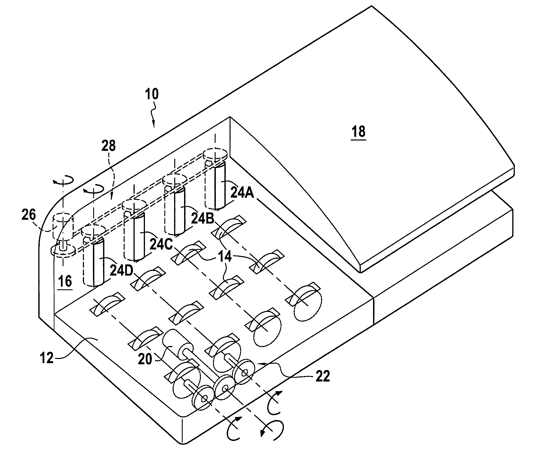
[0019]An automatic mailpiece feed module 10 of the invention is shown in FIG. 1. Conventionally, such a feed module for a franking machine has a feed zone that is formed essentially of a mailpiece-receiving bed 12 designed to receive a stack of mailpieces and provided with conveyor rollers 14 for driving said mailpieces downstream (and along a longitudinal referencing wall 16) to a separation and conveying zone including a separator device 18 in which said mailpieces are extracted one-by-one from the stack of articles and are then conveyed downstream by other conveyor rollers (not shown) that are, in general, disposed at the outlet of said separation zone. The conveyor rollers are actuated by first motor-drive means 20 via a suitable drive train 22.

[0020]The separator device conventionally includes a hinged guide mounted to pivot against resilient means and co-operating with a plurality of opposing selection rollers to select a single mailpiece on its own and to convey it downstream...


PUM

PropertyMeasurementUnit
thicknessesaaaaaaaaaa
thicknessaaaaaaaaaa
heightaaaaaaaaaa

Abstract

A mailpiece feed device comprising a mailpiece-receiving deck for receiving a stack of mailpieces, conveyor rollers for conveying the mailpieces along a longitudinal referencing wall and towards a separator device designed to separate the mailpieces one-by-one from said stack of mailpieces and to convey them downstream, and, incorporated vertically in said longitudinal referencing wall, at least one friction roller of varying roughness, with its coefficient of friction decreasing from the top to the bottom of said longitudinal referencing wall.

Description

TECHNICAL FIELD[0001]The present invention relates to the field of mail handling, and it relates more particularly to an automatic feed module, or feeder, of a mailpiece franking machine or “postage meter”.PRIOR ART[0002]Conventionally, a franking machine must be adapted to receive various types of mailpieces, such as documents, letters, or envelopes of various thicknesses, typically in the range 0.1 millimeters (mm) to 20 mm. For this purpose, on the upstream side, it is often provided with an automatic feed module, such as the feed module described in Patent EP 0 856 483 granted to the Applicant, making it possible, in particular, to convey the mailpieces at various speeds, and usually including means for receiving / stacking, selecting, conveying, and possibly closing said mailpieces.[0003]Selection is generally performed by a single guide and the force with which that guide presses against the mailpieces determines the quality of selection. For mailpieces of small thickness, typic...

Claims


Application Information

Patent Timeline
Patent Type & Authority Applications(United States)
IPC IPC(8): B65H3/00B65G59/00B65H3/52
CPCB65H1/06B65H1/22B65H3/063B65H3/56B65H2301/4423B65H2701/1916B65H2404/5311B65H2404/54B65H2404/743B65H2405/1142B65H2404/1321
Inventor CLARIS, YANNICK
Owner NEOPOST TECH SA
Why Eureka
Try Eureka