Lane keeping assist device and lane keeping assist method

Active Publication Date: 2011-01-20
NISSAN MOTOR CO LTD
View PDF8 Cites 76 Cited by
  • Summary
  • Abstract
  • Description
  • Claims
  • Application Information

AI Technical Summary

Benefits of technology

[0007]Conversely, in order to lessen the awkward feeling of the control intervention when the angle deviation to the departure avoidance side occurs, if the control gain is set small, the control intervention when the angle deviation to the departure side occurs becomes weak, and the departure prevention effec

Problems solved by technology

That is, there is a possibility that this will give an occupant an awkward feeling or an

Method used


Image

  • Lane keeping assist device and lane keeping assist method
  • Lane keeping assist device and lane keeping assist method
  • Lane keeping assist device and lane keeping assist method

Examples


second embodiment

[0242]Next, a second embodiment will be explained with reference to the drawings. Here, the same component as the first embodiment will be explained using the same reference sign.

[0243](Configuration)

[0244]A basic configuration of the present embodiment is similar to the above first embodiment. However, the process at step S200 in the lane keeping assist controller 15 is different.

[0245]The other configuration is the same as the above first embodiment.

[0246]The process at step S200 in the second embodiment will be explained.

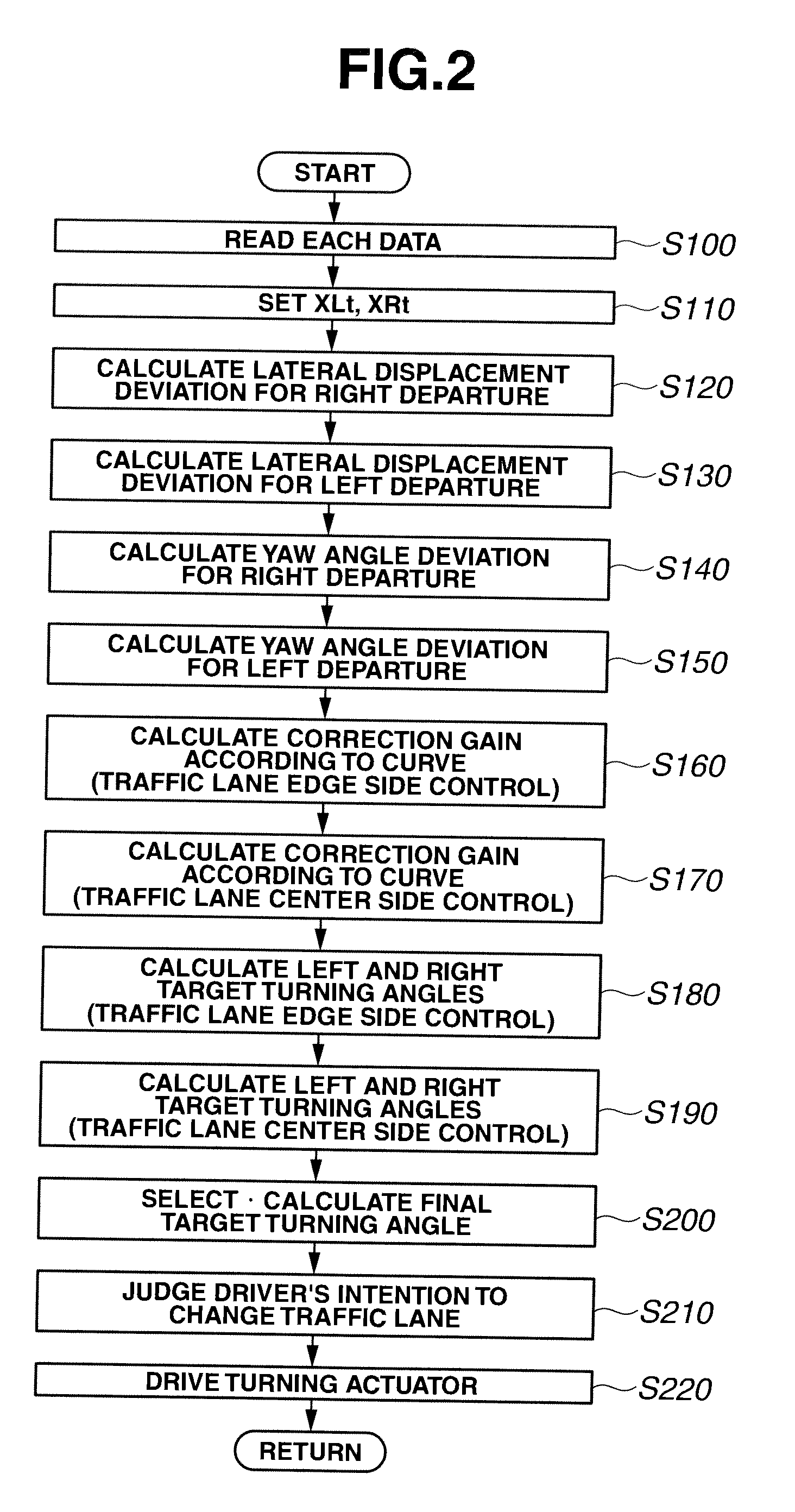
[0247]This step S200 is an operation part that calculates the final target turning angle φt. In the first embodiment, the final target turning angle φt is calculated by the sum of the left and right target turning angle φL_Lt, φL_Rt by the traffic lane edge side control calculated at step S180 and the left and right target turning angles by the traffic lane center side control calculated at step S190 with the weight added to each target turning angle.

[0248]In con...

third embodiment

[0312]Next, a third embodiment will be explained with reference to the drawings. Here, the same component as the above embodiments will be explained using the same reference sign.

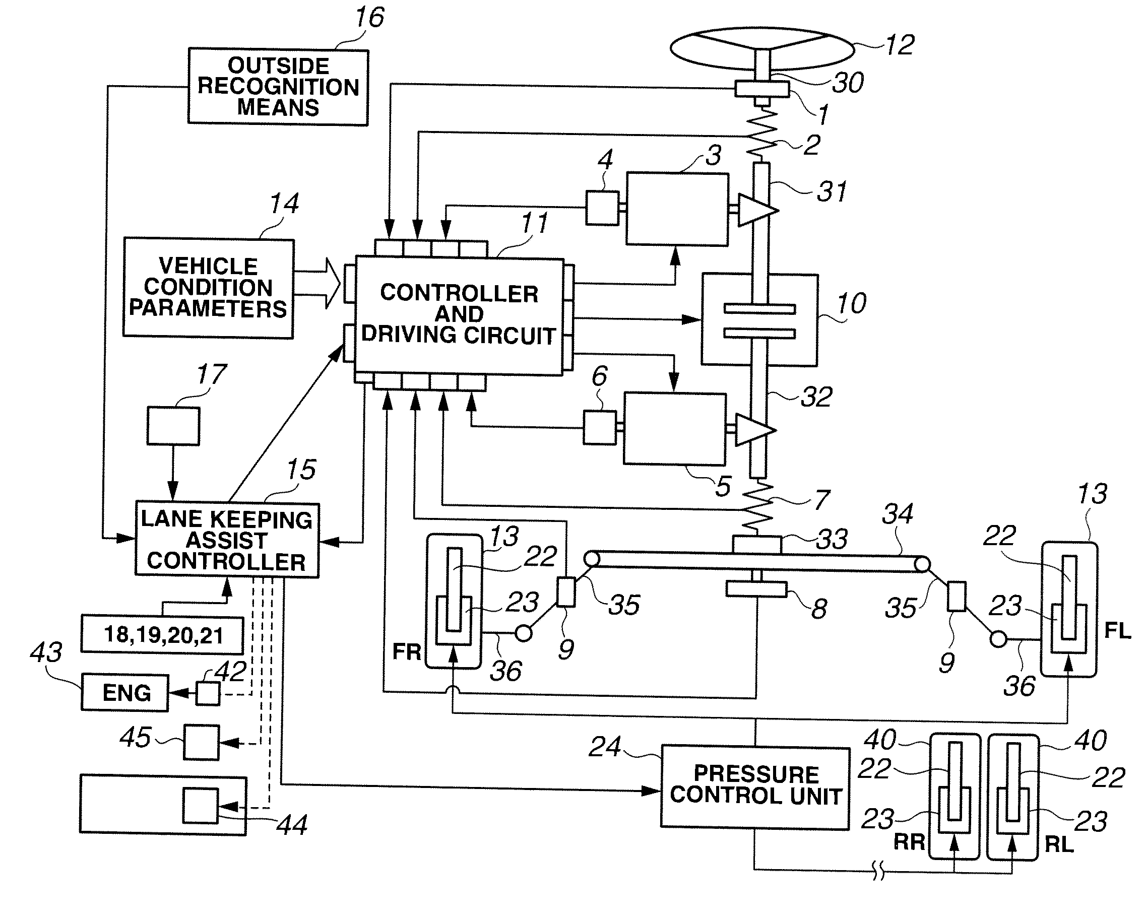
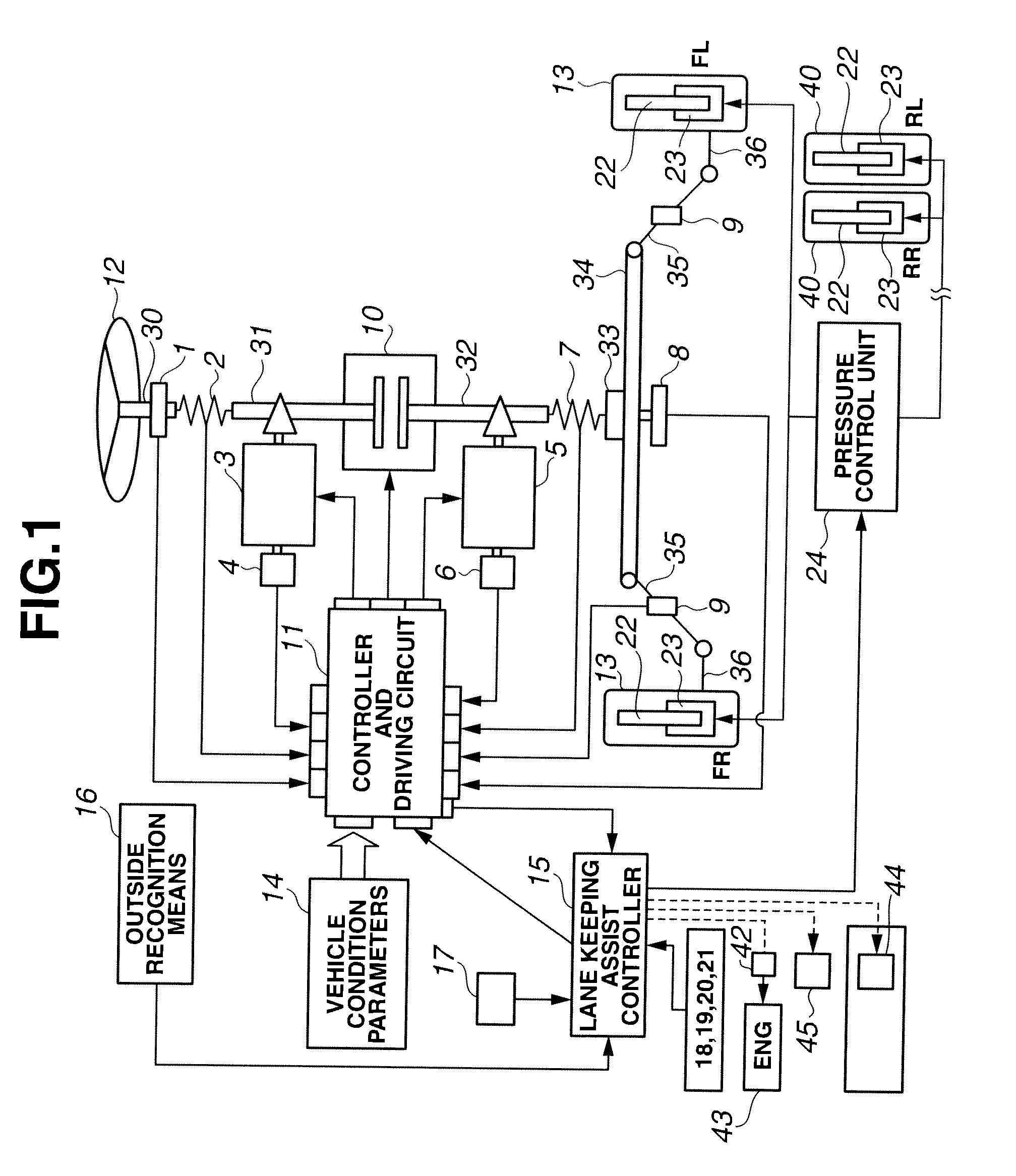
[0313]The configuration of the vehicle to which a lane keeping assist device of the present embodiment is applied is the same as the first embodiment. Therefore, an explanation of the configuration of the vehicle is omitted.

[0314]Then the lane keeping assist device is provided for the vehicle having the above system configuration.

[0315]The configuration will be explained next.

[0316]A monocular camera with image processing function is mounted on the vehicle. This monocular camera with image processing function is an outside recognition means 16 to detect a position of the vehicle. The monocular camera with image processing function captures the road ahead of the vehicle. The monocular camera judges a road condition from the captured camera image, and outputs a signal concerning the vehicle position in the tr...

fourth embodiment

[0479]Next, a fourth embodiment will be explained with reference to the drawings. Here, the same component as the first embodiment will be explained using the same reference sign.

[0480]In the control in the above first to third embodiments, cases where the behavior control of the vehicle is performed, as driving support of the driver, are exemplified.

[0481]Here, when actually executing the vehicle behavior control, if only the vehicle behavior control is performed without attracting the attention, which the driver can recognize, to the driver, there is a possibility that the driver will feel the awkward feeling.

[0482]In the present embodiment, an example that deals with this matter will be explained.

[0483]Process in the lane keeping assist controller of the present embodiment will be explained with reference to FIG. 17.

[0484]Processes from step S100 to step S200 are the same as those in the lane keeping assist controller of the first embodiment.

[0485]In the lane keeping assist contr...


PUM


Abstract

Lateral displacement reference positions LXL, LXR are set on left and right from a center in a width direction of a traffic lane L where a vehicle travels. Then, at least in a case where the vehicle is positioned on an inner side of the left and right lateral displacement reference position LXL, LXR, the vehicle is feedback-controlled so as to decrease a yaw angle deviation. Further, in a case where the vehicle is positioned at an outer side of the left and right lateral displacement reference position LXL, LXR with respect to the traffic lane center, the feedback control is performed so as to decrease the angle deviation and a lateral displacement deviation.

Description

TECHNICAL FIELD[0001]The present invention relates to a lane keeping assist device and a lane keeping assist method which enable a vehicle to travel along a traffic lane and prevent the vehicle from departing from the traffic lane.BACKGROUND ART[0002]As a lane keeping assist device, for example, its invention has been disclosed in a Patent Document 1.[0003]An art disclosed in this Patent Document 1 is an art that controls a turning angle of steered road wheels so that an angle deviation between a travelling direction of the vehicle and the traffic lane decreases. An object of the invention in Patent Document 1 is to prevent the vehicle from departing from the traffic lane.Patent Document 1: Japanese Patent No. JP3729494SUMMARY OF THE INVENTION[0004]As described in the Patent Document 1, in a case where the travelling direction of the vehicle is merely controlled so that the angle deviation with respect to the traffic lane becomes zero, the same control is executed in both situations...

Claims


Application Information

Patent Timeline
IPC IPC(8): G06F7/00B60T8/17B60W10/00B60W10/04B60W10/06B60W10/18B60W10/188B60W10/20B60W30/00B60W30/12B62D5/04B62D5/30B62D6/00B62D101/00B62D113/00B62D117/00B62D119/00
CPCB60W30/12B60T8/17557B62D15/025B60W40/072B60W2050/0022B60W2520/12B60Y2300/12
Inventor TANGE, SATOSHIKIMURA, TAKESHITAKEDA, YUYANISHIDA, YUKINORI
Owner NISSAN MOTOR CO LTD
Why Eureka
Try Eureka