
Cylinder latching mechanism for revolver

a technology of cylinder and latching mechanism, which is applied in the field of firearms, can solve the problems of difficult to achieve proper alignment and meshing between the trigger and the hammer, little weight savings, and limited previous use of non-metallic materials such as polymers in revolvers, and achieves the effect of high strength

Active Publication Date: 2011-01-27
STURM RUGER & CO INC
View PDF13 Cites 3 Cited by
  • Summary
  • Abstract
  • Description
  • Claims
  • Application Information

AI Technical Summary

Benefits of technology

The use of a polymer-based firing control housing reduces the overall weight of the revolver while maintaining structural integrity and allowing for intricate designs, achieving a significant weight reduction without compromising performance or aesthetics.

Problems solved by technology

In practice, it is difficult to achieve proper alignment and meshing between the trigger and hammer operably coupled thereto if these firing control components were mounted in separate frames.
Because the metal cylinder frame is far heavier than the grip frame even in two-piece revolver frame constructions, there was little weight savings possible by simply making the grip frame of a lighter material.
Although semi-automatic pistols have used non-metallic polymer grip frames in combination with metal reciprocating slides mounted thereon, the concept of using dual materials in revolvers has not been used heretofore because of the limited potential gains in weight reduction achievable using the foregoing conventional revolver construction with mounting the firing control components in the cylinder frame.
Previous use of non-metallic materials such as polymers in revolvers has been largely limited to the non-structural handgrips which typically are attached to the metal grip frame via threaded fasteners.

Method used


Image

  • Cylinder latching mechanism for revolver
  • Cylinder latching mechanism for revolver
  • Cylinder latching mechanism for revolver

Examples


Embodiment Construction

[0022]The features and benefits of the invention are illustrated and described herein by reference to preferred embodiments. This description of preferred embodiments is intended to be read in connection with the accompanying drawings, which are to be considered part of the entire written description. In the description of embodiments disclosed herein, any reference to direction or orientation is merely intended for convenience of description and is not intended in any way to limit the scope of the present invention. Relative terms such as “lower,”“upper,”“horizontal,”“vertical,”“forward,”“rearward,”“front,”“back,”“above,”“below,”“up,”“down,”“top” and “bottom” as well as derivative thereof (e.g., “horizontally,”“downwardly,”“upwardly,” etc.) should be construed to refer to the orientation as then described or as shown in the drawing under discussion. These relative terms are for convenience of description only and do not require that the apparatus be constructed or operated in a par...


PUM


Abstract

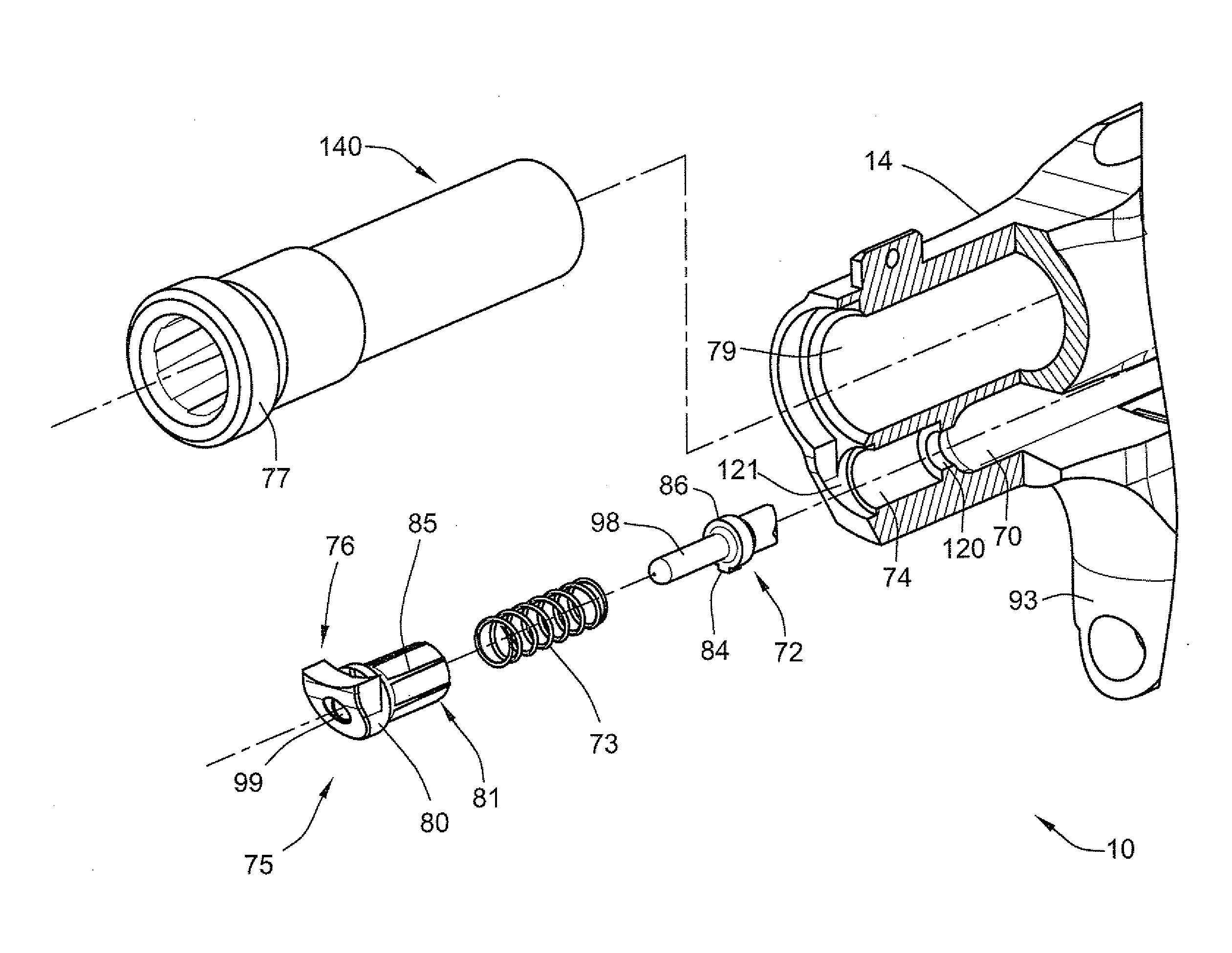
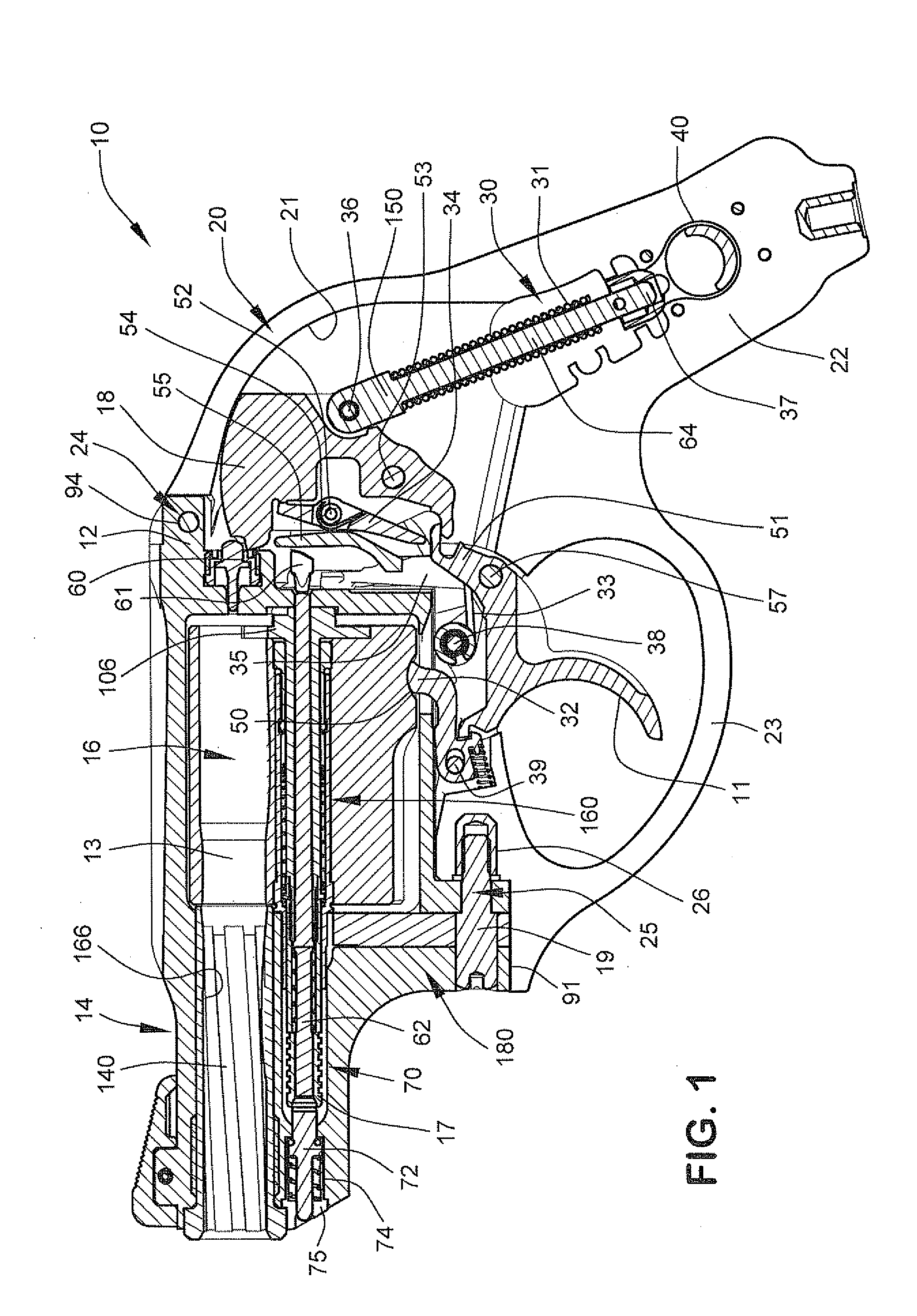
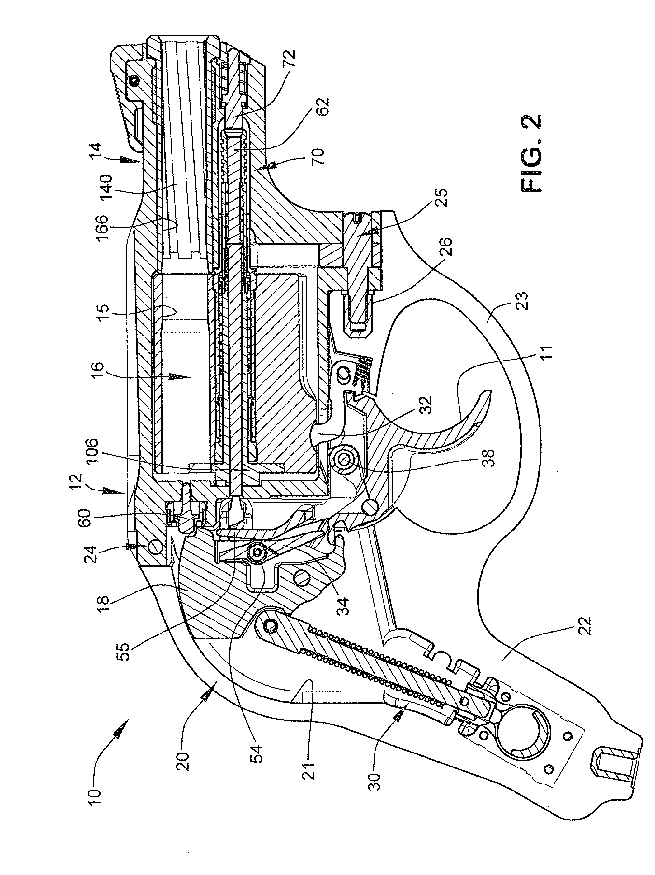
A revolver with latching mechanism for swing-out type cylinder. The revolver includes a frame, a rotatable cylinder movable from a ready-to-fire position in the frame to a loading position laterally displaced outwards from the frame, and a latching member retained in the frame by a barrel insert that defines a bullet bore. In one embodiment, the latching member may be a spring-loaded plunger movable from a locked position in which the cylinder is locked in the ready-to-fire position to an unlocked position in which the cylinder is movable to the loading position. A cylinder crane pivotally mounts the cylinder in the frame and moving the plunger to the unlocked position allows the cylinder crane to be swung out laterally from the frame by a user. In one embodiment, the plunger is held in the frame by a retaining plug engaged by the barrel insert.

Description

CROSS-REFERENCE TO RELATED APPLICATIONS[0001]The present application claims priority to U.S. Provisional Application No. 60 / 955,723 filed Aug. 14, 2007, which is incorporated herein by reference in its entirety.BACKGROUND OF THE INVENTION[0002]The present invention generally relates to firearms, and more particularly to a cylinder retaining or latching mechanism for a revolver.[0003]Revolvers typically include a cylinder frame which rotatably supports a revolving cylinder with a plurality of chambers for holding cartridges and a grip frame that provides a structure for mounting and supporting a hand grip attached thereto at the rear of the revolver. The barrel of the revolver is also mounted to the front of or forms part of the cylinder frame.[0004]In some designs such as heavy duty revolvers capable of firing magnum-type loads, a strong one-piece integral frame construction is often preferred which combines both the cylinder and grip frames into one integral unit for added durabili...

Claims


Application Information

Patent Timeline
Patent Type & Authority Applications(United States)
IPC IPC(8): F41C3/14
CPCF41A3/66F41A19/42F41C23/16F41C3/14F41C23/10F41A21/488
Inventor ZAJK, JOSEPH J.
Owner STURM RUGER & CO INC
Learn More