Vibration damping apparatus
a technology of vibration damping and damping chamber, which is applied in the direction of shock absorbers, mechanical devices, dampers with inertia effect, etc., can solve the problems of difficult suppression of vibration and the inability to obtain the expected vibration suppressing effect, and achieve the effect of suppressing vibration
- Summary
- Abstract
- Description
- Claims
- Application Information
AI Technical Summary
Benefits of technology
Problems solved by technology
Method used
Image

Examples
first embodiment
Constitution of Vibration Damping Apparatus
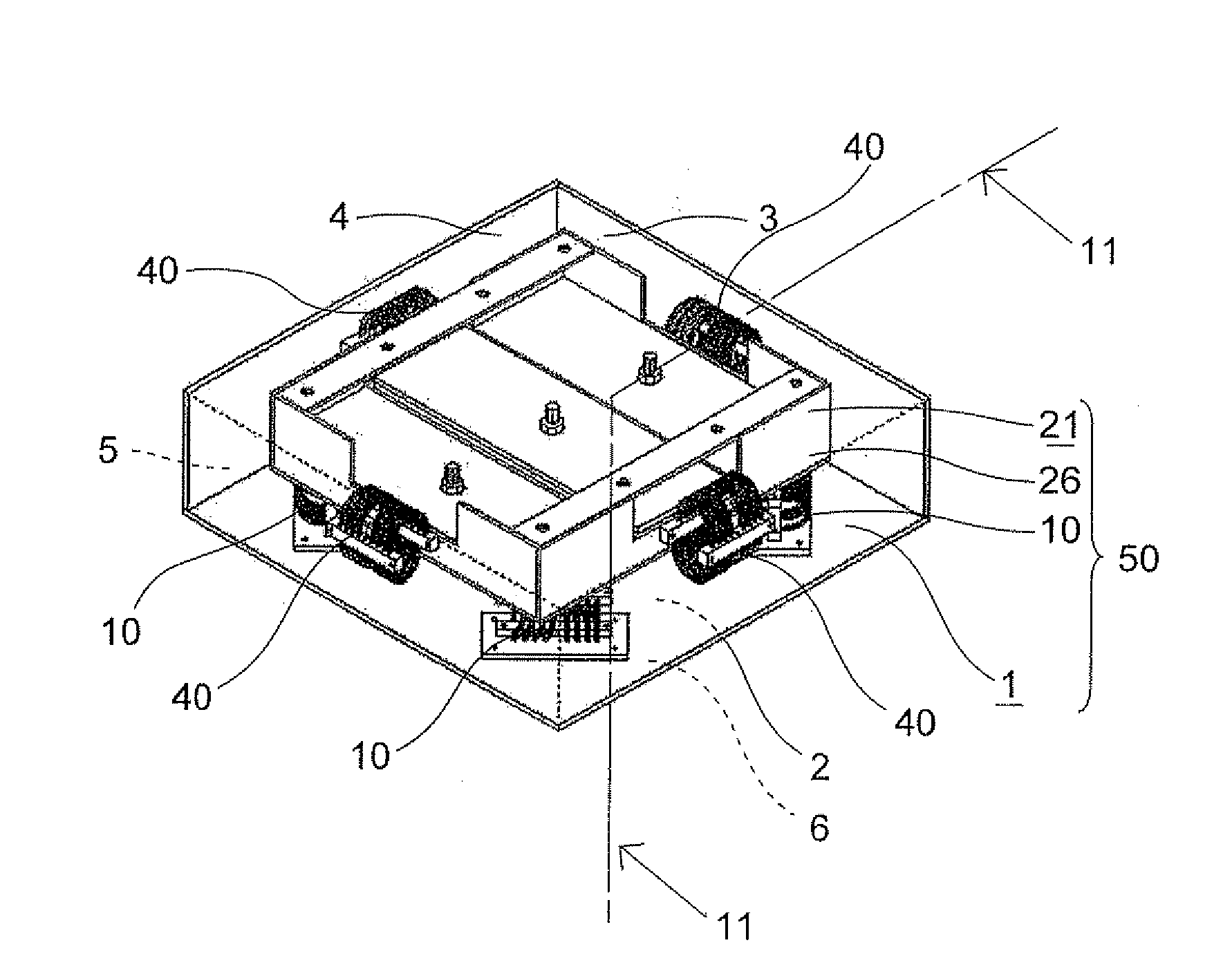
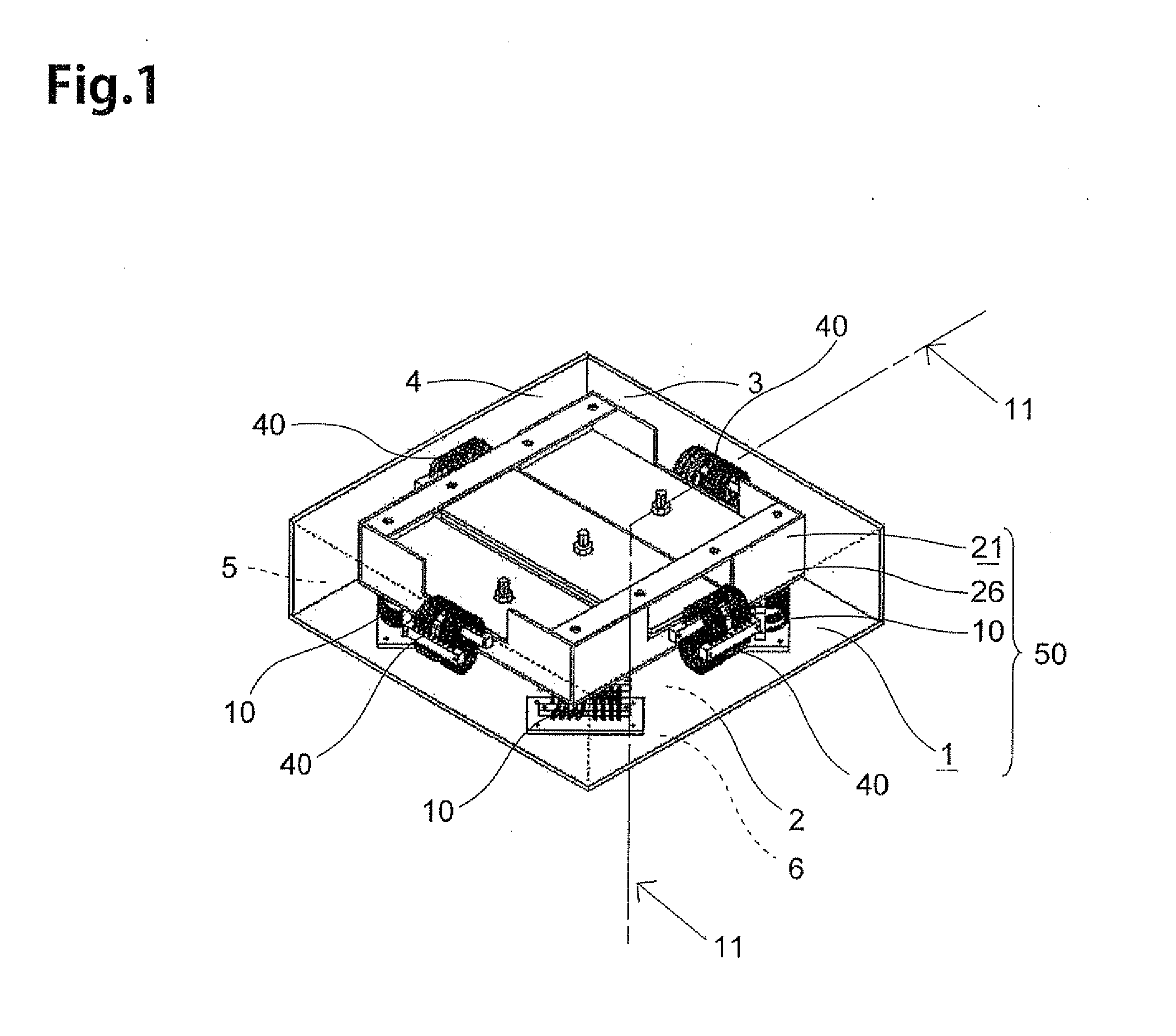
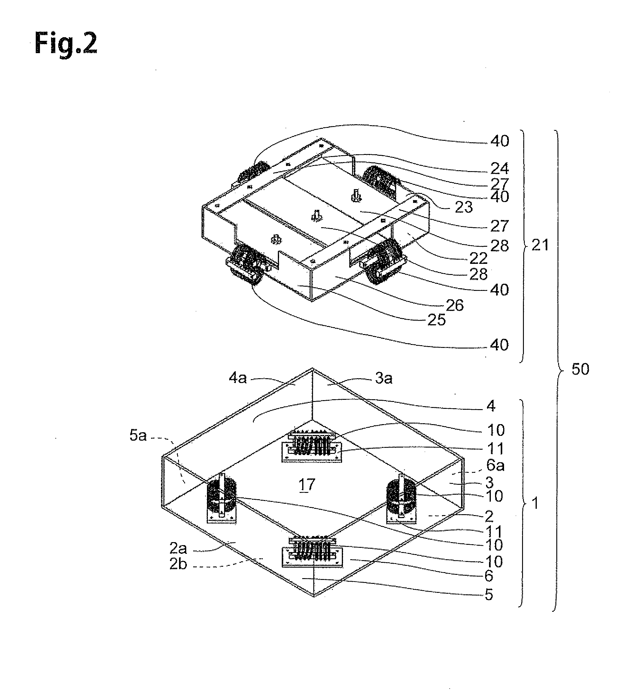
[0061]The constitution of a vibration damping apparatus according to a first embodiment of the present invention will be described with reference to drawings. FIG. 1 is a perspective view illustrating a constitution of a vibration damping apparatus 50 according to a first embodiment of the present invention, and FIG. 2 is an exploded perspective view illustrating a constitution of the vibration damping apparatus 50. As illustrated in FIG. 1, FIG. 2, the vibration damping apparatus 50 has a lower unit 1 and an upper unit 21.
[0062]The lower unit 1 has a base member 2, four wall members 3, 4, 5, 6, four helical structure bodies 10, and four support plates 11.
[0063]The base member 2 is a plate formed in a square shape using metal such as steel and has a flat front face 2a and a flat rear face 2b, as illustrated in detail in FIG. 2 and FIG. 3. This base member 2 is a first base member in the present invention and constitutes a bottom portion of ...
modified example 1
[0103]Next, a modified example of the vibration damping apparatus 50 will be described referring to FIG. 13. FIG. 13 (a) is a plan view illustrating a base member 122 and a wire spring 12 according to the modified example, which are partially omitted. FIG. 13(b) is a perspective view illustrating a wire spring 112 according to the modified example.
[0104]While the helical structure bodies 40 are fixed to the wall members 23, 24, 25, 26 in the above-described vibration damping apparatus 50, the wire springs 12 may be fixed to a circumferential edge portion 122a of the base member 122 so that the loop portions 12a extend out from the circumferential edge portion 122a and stand up as illustrated in FIG. 13 (a). The base member 122 is a plate similar to the base member 22, but a plurality of through holes 122b corresponding to the loop portions 12a are formed in the circumferential edge portion 122a. By inserting the loop portions 12a through the respective through holes 122b, only one o...
modified example 2
[0108]Next, another modified example of the vibration damping apparatus 50 will be described referring to FIG. 14. FIG. 14 (a) is a plan view illustrating a state that four wire springs 12 are fixed to the base member 2. FIG. 14 (b) is a plan view illustrating a state that the four wire springs are fixed in a different arrangement. FIG. 14 (c) is a perspective view illustrating the base member 2 on which four wire rings 114 are fixed.
[0109]In the above-described vibration damping apparatus 50, the helical structure bodies 10 are fixed in the arrangement illustrated in FIG. 3. However, as illustrated in FIG. 14 (a), the four wire springs 12 may be fixed to the base member 2 at equal intervals. Further, as illustrated in FIG. 14 (b), the four wire springs 12 may be arranged at equal distances from the center p on diagonal lines.
[0110]Moreover, both ends of the rope member 16 may be connected to make a wire ring 114 of one winding, and this wire ring 114 may be fixed to stand up along ...
PUM
 Abstract
Description
Claims
Application Information
 - R&D
- Intellectual Property
- Life Sciences
- Materials
- Tech Scout
- Unparalleled Data Quality
- Higher Quality Content
- 60% Fewer Hallucinations
Browse by: Latest US Patents, China's latest patents, Technical Efficacy Thesaurus, Application Domain, Technology Topic, Popular Technical Reports.
© 2025 PatSnap. All rights reserved.Legal|Privacy policy|Modern Slavery Act Transparency Statement|Sitemap|About US| Contact US: help@patsnap.com