Helical broach for roughing

a technology of helical broaches and rakes, which is applied in the direction of gear teeth, manufacturing tools, gear teeth, etc., can solve the problems of large difference in cutting performance between the tooth faces on both sides of the rake face, unbalanced cutting in the right and left sides of the toothed gear, and hinder the improvement of the accuracy of machining using the helical broach, so as to reduce the difference in cutting performance and improve the machining accuracy. , the effect o

Inactive Publication Date: 2011-01-27
MITSUBISHI HEAVY IND MACHINE TOOL CO LTD
View PDF5 Cites 17 Cited by
  • Summary
  • Abstract
  • Description
  • Claims
  • Application Information

AI Technical Summary

Benefits of technology

[0015]The helical broach for roughing according to the first invention mentioned above is a helical broach for roughing that includes a cutting tooth part in which multiple spline teeth are arranged side by side in an axial direction. The spline teeth each include cutting teeth which are arranged at a predetermined helix angle. The cutting teeth each have an acute angle portion and an obtuse angle portion on both sides thereof in a circumferential direction. The cutting teeth disposed on part of the spline teeth in the circumferential direction are each formed in such a way that its height on the acute angle portion side differs from that on the obtuse angle portion side. The part of the spline teeth are spline teeth disposed sequentially from a leading one of the spline teeth. The cutting teeth of the other part of the spline teeth are each formed in such a way that its height stays constant in the circumferential direction. A prepared hole may be first machined with the part of the spline teeth, which achieves balanced cutting by reducing the difference in cutting performance between the acute angle portion side and the obtuse angle portion side of each cutting tooth. Then, machining may be performed with the other part of the spline teeth to obtain a final shape. This reduces an adverse influence on the tooth profile accuracy and the tooth trace accuracy attributable to the difference in cutting performance, thereby allowing improvement in the machining accuracy.
[0016]Also, in the helical broach for roughing according to the second invention mentioned above, part or all of the cutting teeth on circumferences of the part of the spline teeth are each formed in such a way that its height on the acute angle portion side differs from that on the obtuse angle portion si...

Problems solved by technology

In machining using these helical broaches, it has been known that a helix angle causes a difference in cutting performance between the left side and the right side (an acute angle portion side and an obtuse angle portion side) of a toothed gear, which may in turn lead to unbalanced cutting in the right and left sides of the toothed gear.
This angular difference between both sides of the rake face causes the unbalanced cutting in machining using the helical...

Method used


Image

  • Helical broach for roughing
  • Helical broach for roughing
  • Helical broach for roughing

Examples


examples

[0027]An embodiment of the present invention will be described using FIGS. 1 to 5.

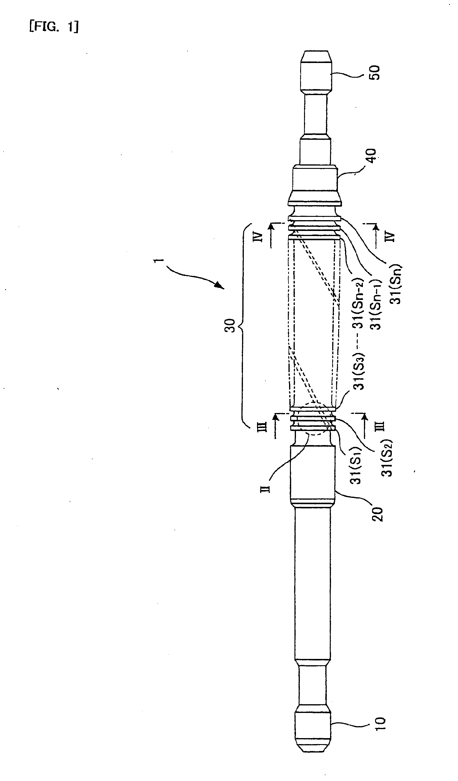
[0028]As shown in FIG. 1, a helical broach 1 for roughing in the embodiment has a configuration integrally formed, mainly, of a pull end 10, a front pilot 20, a cutting tooth part 30 where many spline teeth 31 (S1 to Sn) are arranged, a rear pilot 40, and a follower end 50.

[0029]The pull end 10 is a part provided to attach the helical broach 1 for roughing to a pull head of a broaching machine. The front pilot 20 is a part to guide a prepared hole formed in advance in a work piece 2 (see FIG. 5) to the first spline tooth 31 (S1), i.e., the leading tooth of the helical broach 1 for roughing.

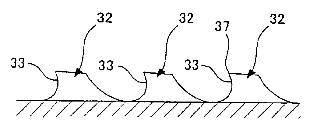
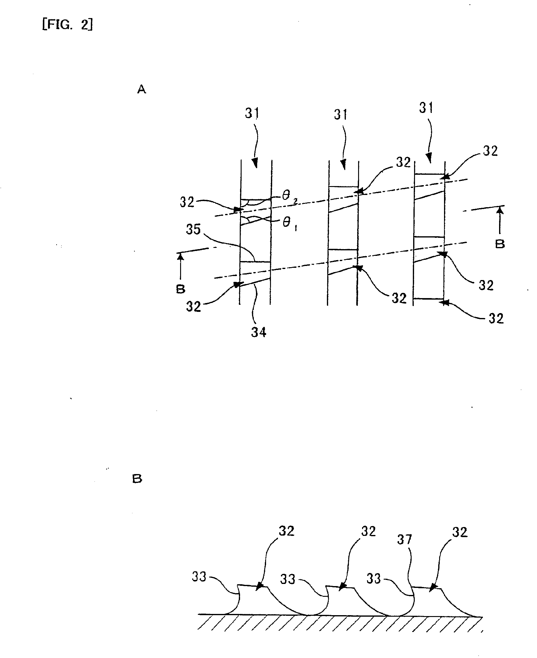
[0030]The cutting tooth part 30 is configured such that the many (n teeth in the embodiment) spline teeth 31 are arranged side by side in the axial direction. As shown in FIGS. 2 to 4, these spline teeth 31 each include a predetermined number of cutting teeth 32. The spline teeth 31 are arranged in the ascending orde...


PUM

PropertyMeasurementUnit
Widthaaaaaaaaaa
Heightaaaaaaaaaa

Abstract

A helical broach 1 for roughing includes a cutting tooth part 30 in which n spline teeth 31 are arranged side by side in an axial direction. The spline teeth 31 each include cutting teeth 32 which are arranged at a predetermined helix angle. The cutting teeth 32 each have an acute angle portion and an obtuse angle portion on both sides thereof in a circumferential direction. The cutting teeth disposed on the first to n−1th spline teeth 31 (S1 to Sn−1) in the circumferential direction are each formed in such a way that its height on the acute angle portion side differs from that on the obtuse angle portion side. The cutting teeth (Sn) of the nth spline tooth (Sn) are each formed in such a way that its height stays constant in the circumferential direction.

Description

TECHNICAL FIELD [0001]The present invention relates to a helical broach for roughing.BACKGROUND ART [0002]Heretofore, roughing and finishing using helical broaches have been a mainstream in manufacture of internal gears. Helical broaches each perform cutting on a prepared hole formed in advance in a work piece by use of its cutting teeth which are larger gradually and sequentially in an outer radial direction and in a tooth thickness direction. Various studies have been made on helical broaches. There exist many variations of helical broaches such as: a type which includes a set of several separate units for roughing and finishing; a type in which a roughing cutting tooth group and a finishing cutting tooth group are put together into one unit; as well as an assembly type in which a roughing cutting tooth group and a finishing cutting tooth group are assembled and integrated together.[0003]In machining using these helical broaches, it has been known that a helix angle causes a diff...

Claims


Application Information

Patent Timeline
IPC IPC(8): B23P15/42
CPCB23D43/005B23F1/08Y10T407/1685Y10T407/16Y10T407/1671B23F21/26
Inventor KATSUKI, YASUHITO
Owner MITSUBISHI HEAVY IND MACHINE TOOL CO LTD
Why Eureka
Try Eureka