Modular rotor blade for a power-generating turbine and a method for assembling a power-generating turbine with modular rotor blades

a technology of modular rotor blades and power-generating turbines, which is applied in the direction of machines/engines, manufacturing tools, forging/pressing/hammering apparatus, etc., can solve the problem that wind turbine blades greater than 50 m in length cannot be transported over land using conventional equipment and technology, and achieve the effect of reducing transportation costs, reducing the cost of installation of wind turbines, and reducing the cost of large wind turbine blades

Inactive Publication Date: 2011-01-27
CLIPPER WINDPOWER INC
View PDF6 Cites 36 Cited by
  • Summary
  • Abstract
  • Description
  • Claims
  • Application Information

AI Technical Summary

Benefits of technology

With respect to a method for assembling a power generating turbine with modular rotor blades, the method comprises: the steps of manufacturing rotor blades in at least two rotor blade sections, wherein adjacent rotor blade sections have connecting parts for mounting said adjacent blade sections together; transporting said blade sections to a site; providing, at said site, a turbine on a structure that is held stationary with reference to said fluid flow, said turbine including a rotor hub and a rotor having provisions to mount first rotor blade sections to said rotor hub; connecting said first blade sections to said rotor hub; and attaching second rotor blade sections to first blade sections by mounting the connecting parts of adjacent rotor blade sections together by means of at least one conical bolt being tensioned by at least one tensioning means passing through the conical bolt. This method allows large wind turbine blades to be manufactured and transported in multiple pieces and, thus, has the advantage of reduced transportation costs for large wind turbine blades.
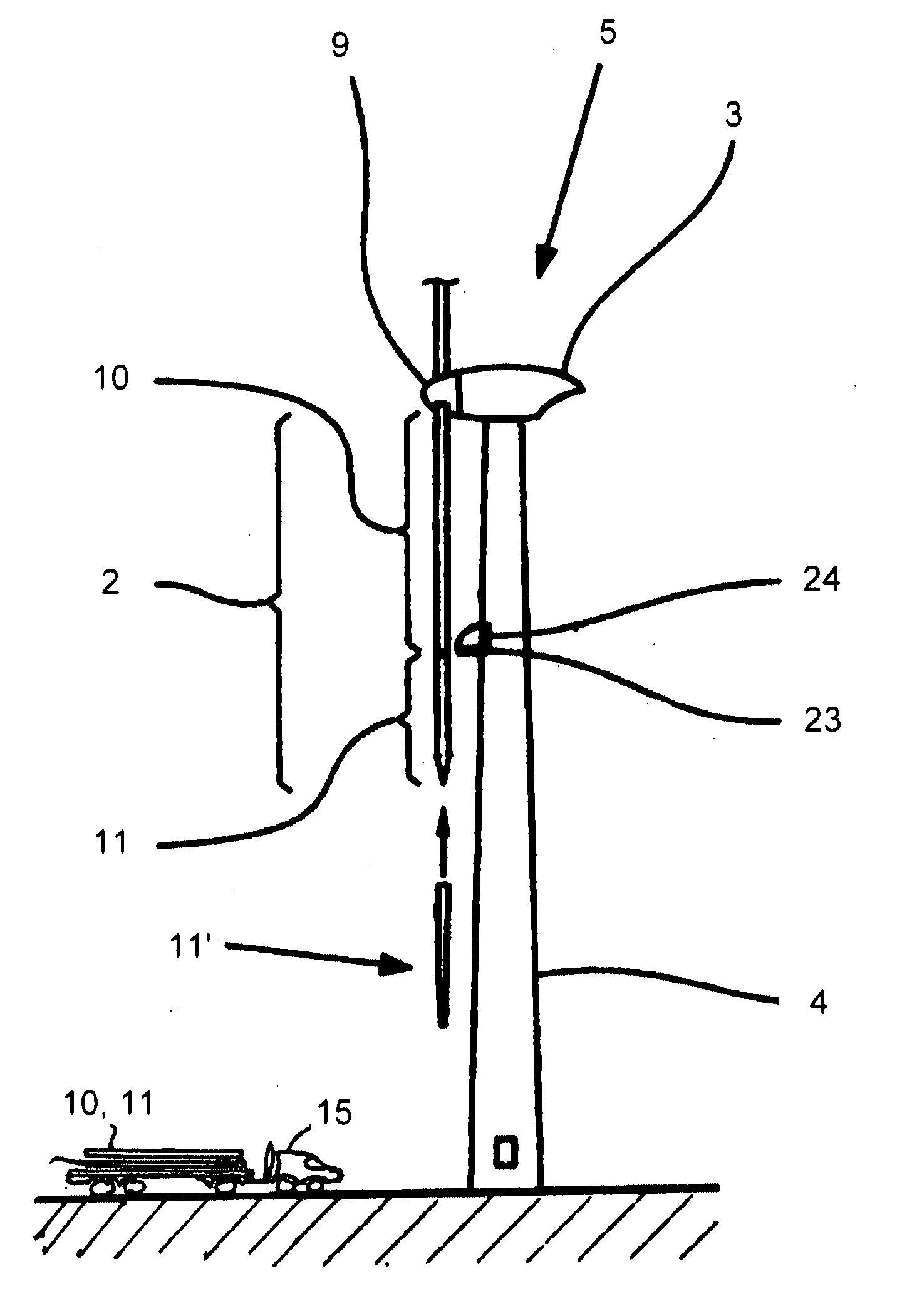
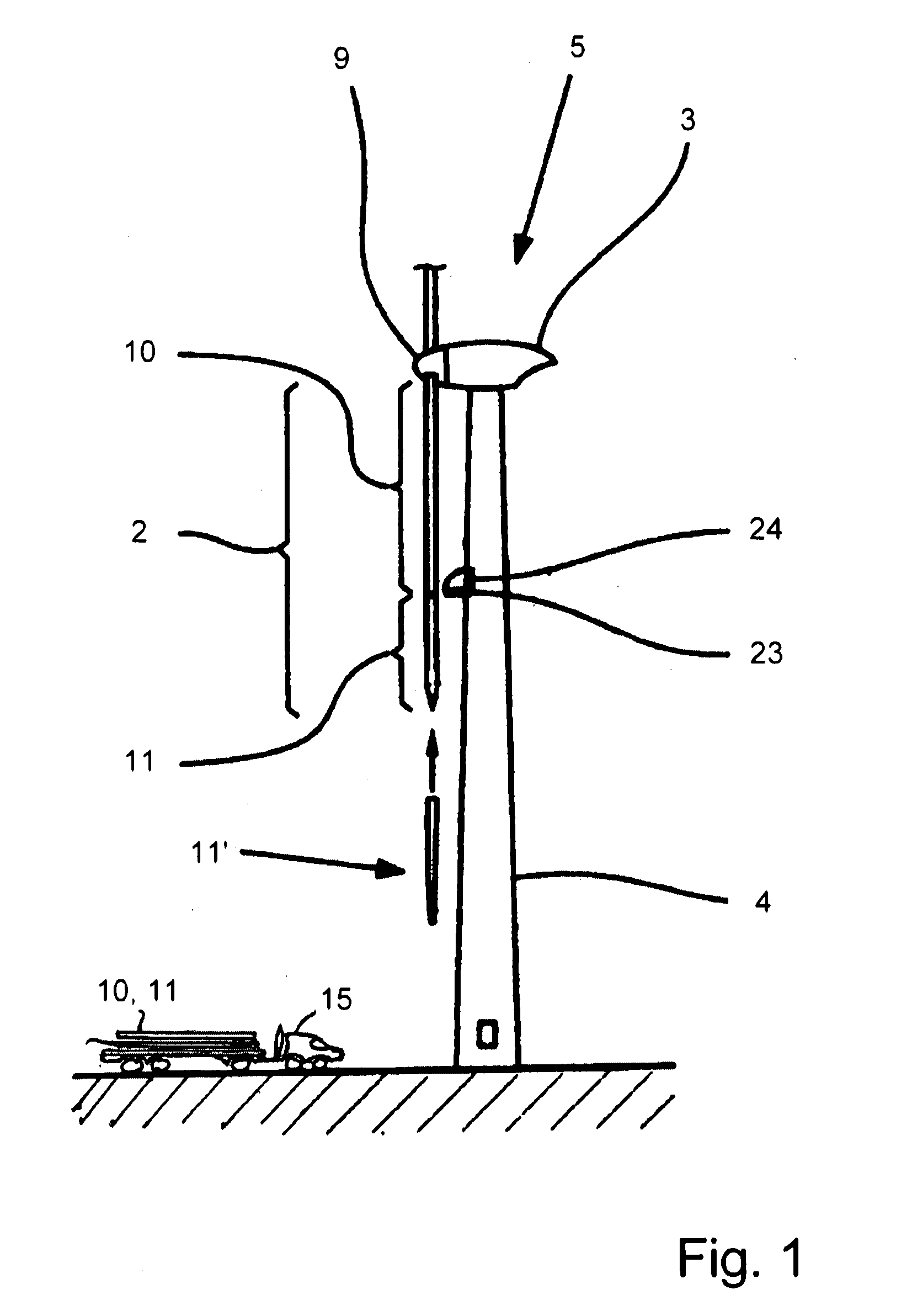
As a further aspect of the method according to the present invention, the second rotor blade sections are lifted by a hoist within a nacelle before attaching the second rotor blade sections to the first rotor blade sections. For example in the case of a wind turbine, this aspect has the advantage that no tower crane or helicopter is needed in order to assemble the modular rotor blades thereby reducing the costs for installation of the wind turbine.
According to a further step of the method of the present invention, the method comprises the step of attaching a blade tip to said second blade section. Due to this feature, large wind turbines can be manufactured and transported in multiple pieces thereby reducing the costs for transportation.
Accordingly, the present invention provides a design of an easily re- and post-tensioning joint of modular rotor blades.
This design prevents all movements within the joint and prevents the structural fatigue that would be caused by such movements. The invention has the advantage that it lowers the transportation costs of current wind turbine blades exceeding 50 meters or more in length, and allows larger wind turbine blades to be transported on existing air, land and water travel routes. The invention has the further advantage that the joint of adjacent rotor blade sections allows large wind turbine blades to be manufactured and transported in multiple pieces without associated maintenance costs for re-tensioning of joints. Further, the invention has the advantage of reduced transportation costs for large wind turbine blades. Furthermore, the invention has the advantage of allowing outboard blades severely damaged due to a lightening strike to be replaced without replacing the whole blade. Finally, the invention has the advantage of not requiring annual maintenance.

Problems solved by technology

Wind turbine blades greater than 50 m in length cannot be transported over land using conventional equipment and technology.

Method used


Image

  • Modular rotor blade for a power-generating turbine and a method for assembling a power-generating turbine with modular rotor blades
  • Modular rotor blade for a power-generating turbine and a method for assembling a power-generating turbine with modular rotor blades
  • Modular rotor blade for a power-generating turbine and a method for assembling a power-generating turbine with modular rotor blades

Examples


first embodiment

With respect to FIG. 3, which is a perspective view of the modular rotor blade of FIG. 1 according to the present invention, the modular rotor blade comprises the first rotor blade section 10, which connects to the (not shown) rotor hub 9, and the second rotor blade section 11 that connects to the first rotor blade section 10 by, inter alia, means of a connecting part 14 and a connecting part 16.

In this embodiment the connecting part 14 of the second rotor blade section 11, the second connecting part 14, is formed as a beam with two side walls, and upper and lower sides (connecting part 14 can also be referred to as a “tongue”), and the connecting part 16 of the first rotor blade section 10, the first connecting part 16, is formed as a receptacle (and can also be referred to as a “fork”). The first connecting part 16 is adapted to receive the second connecting part 14, and the cross section of the second connecting part 14 is adjusted to the cross section of the first connecting par...

second embodiment

With respect to FIG. 7, there is shown a detailed view of the present invention. The connecting part 16 of the first rotor blade section 10 encloses the connecting part 14 of the second rotor blade section 11. Both connecting parts 14, 16 comprise two conical through holes. In the connected state of the rotor blade sections 10, 11 the connecting parts 14, 16 rest against each other such that the conical through holes of the enclosing connecting part 16 are aligned with the two through holes of the enclosed connecting part 14, thereby defining two continuous conical connecting through holes, i.e. the through holes of the connecting parts, and therefore the continuous conical connecting through holes are arranged on the same longitudinal axis in the connected state of the rotor blade sections 10, 11. The through holes of the connecting parts 14, 16 are provided in such a manner that the openings with the greater diameter widens towards the outer surfaces of the connecting parts 14, 16...

third embodiment

FIG. 8 shows a detailed view of the present invention, wherein the upper half of FIG. 8 is a sectional view through two conical bolts 30, whereas the lower half of FIG. 8 is a top view.

The third embodiment utilizes an enclosing connecting part 16 and an enclosed connecting part 14. In contrast to the second embodiment the enclosed connecting part 14 is solid, i.e. no separate side walls and therefore no space within the connecting part is provided. Accordingly, the enclosed connecting part 14 is not hollow. The enclosing connecting part 16 comprises two conical through holes and the enclosed connecting part 14 comprises one through hole, wherein the through holes are, in the assembled state of the modular rotor blade, arranged on the same longitudinal axis. The through hole of the enclosed connecting part 14 is formed as a double conical through hole, wherein the openings with the greater diameter open up to the outer surfaces of the enclosed connecting part. The conical through hol...


PUM

PropertyMeasurementUnit
lengthaaaaaaaaaa
inclination angleaaaaaaaaaa

Abstract

A modular rotor blade for a power generating turbine allows simple replacement of individual rotor blade sections in case of damage to or malfunction of a section. The modular rotor blade includes at least two rotor blade sections, wherein each rotor blade section includes at least one connecting part having at least one conical opening. The connecting parts of adjacent rotor blade sections rest against each other such that the conical openings of the connecting parts are aligned with each other and form a continuous conical connecting opening. Receiving elements for receiving tensioning elements are arranged at the smaller diameter end of the conical connecting opening. A conical bolt corresponding to the continuous conical connecting opening is arranged therein, and at least one tensioning element passes through the conical bolt and tensions the conical bolt against the receiving element.

Description

BACKGROUND OF THE INVENTION1. Field of the InventionThis invention relates to electric power-generating devices, such as wind turbines and ocean current turbines, and more particularly to a modular rotor blade for a power generating turbine, which has one or more detachable blade sections, which can be detached for shipment and assembled on-site. The invention relates further to a method for assembling a power generating turbine with modular rotor blades.2. Description of the Prior ArtConventional wind turbine rotors utilize blades manufactured as one piece-fixed length blades, joined at a rotating hub. These blades may be of variable pitch (selectively rotatable about their longitudinal axes) in order to alter the angle of attack relative to the incoming fluid flow, principally for power shedding in high-flow velocities.Alternatively, these blades may be fixed pitch or stall-regulated, wherein blade lift and therefore power capture falls off dramatically as wind speeds exceed some ...

Claims


Application Information

Patent Timeline
Patent Type & Authority Applications(United States)
IPC IPC(8): F01D5/14B23P15/04
CPCF03D1/0675F03D11/00F05B2210/16F05B2240/40Y10T29/4932F05B2260/301Y02E10/721Y02E10/722F05B2250/232F05B2240/302F03D80/00Y02E10/72F03D13/40
Inventor GLENN, BRIANDEHLSEN, JAMES G.P.KELLER, WALTERROHM, ANDREASMEHRLE, WOLFGANGSTUCKERT, MARTIN
Owner CLIPPER WINDPOWER INC
Why Eureka
Try Eureka