Method and Devices for Force-Limiting Trigger Mechanism

a trigger mechanism and force-limiting technology, applied in the field of arthroscopic procedures, can solve the problems of reducing the strength of the trigger force, and difficult punching of several tissue types, and causing significant spring recoil

Inactive Publication Date: 2011-01-27
ORTHODYNAMIX
View PDF1 Cites 40 Cited by
  • Summary
  • Abstract
  • Description
  • Claims
  • Application Information

AI Technical Summary

Benefits of technology

[0007]The invention also relates to a method of performing a surgical procedure within a confined body cavity of a patient using a surgical instrument having a handle, an elongate body member extending distally from the handle and terminating in a tool head, a cable engagement arm pivotably attached to the handle by a first pivot, an actuation lever pivotably attached to the cable engagement arm by a second pivot, and a torsion control mechanism configured to resist rotation of the actuation lever about the second pivot when a rotational force is applied to the actuation lever, but to allow such rotation if the rotational force produces a moment about the second pivot exceeding a predetermined limit, the tool head being operable by application of a force to a cable extending from the tool head to the

Problems solved by technology

Several tissue types, specifically the labrum of the hip and the meniscus of the knee, are particularly difficult to punch.
One of the disadvantages associated with spring-loaded guns used for arthroscopic procedures is that sometimes the trigger force exceeds the spring strength.
This can create a significant spring recoil once the spring gun is triggered and the punch jaws are engaged.
In addition to the recoil, the stress created in the jaws of spring-loaded guns used for arthroscopic procedures can lead to breakage of the jaws or other components.
As punch jaws wear down because of stresses incurred in carrying out their normal functions, more force is required to punch through these tough

Method used


Image

  • Method and Devices for Force-Limiting Trigger Mechanism
  • Method and Devices for Force-Limiting Trigger Mechanism
  • Method and Devices for Force-Limiting Trigger Mechanism

Examples


Embodiment Construction

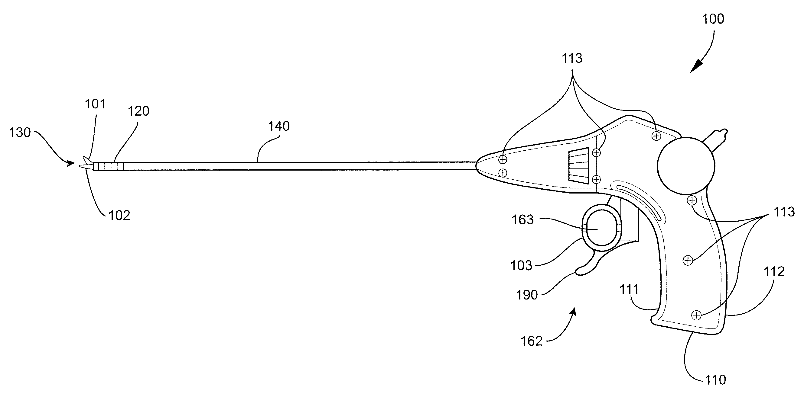
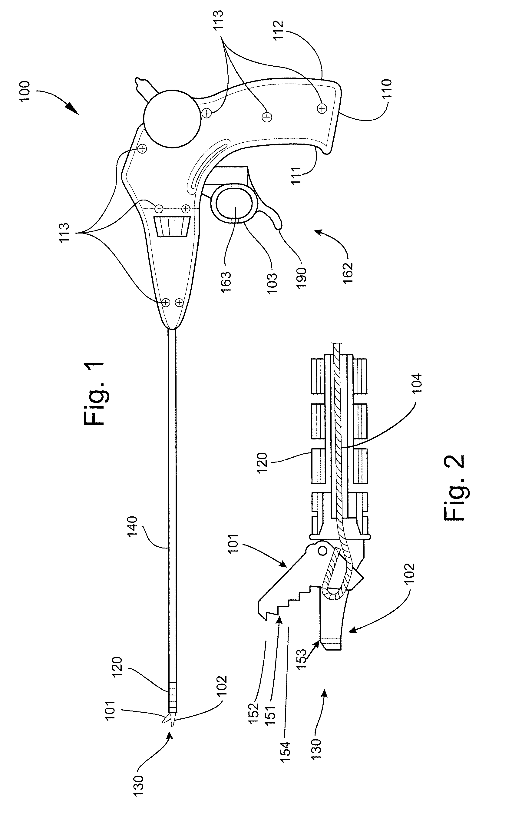
[0016]The devices and methods of the invention are primarily illustrated and described herein by means of devices which have been adapted for use in performing arthroscopic procedures primarily on, but not limited to, the hips, knees, and shoulders. The devices and methods provide access to the internal portions of the distended hip capsule during arthroscopic procedures that are presently not accessible using currently available arthroscopic instruments. The devices and methods can suitably be used to perform arthroscopic procedures not only on the hip, but also on other parts of the body, such as the knee, shoulder, wrist, elbow, etc. The devices are particularly suitable for performing procedures on parts of the body that require flexible access. The devices and methods are not limited to arthroscopy, and can further be used in endoscopic and laparoscopic procedures as well as open surgeries. As described in U.S. patent application Ser. No. 12 / 119,799 filed May 13, 2008 (“the '79...


PUM


Abstract

An actuating mechanism for use with a surgical instrument having a handle, an elongate body member, and a tool head. The actuating mechanism comprises a cable engagement arm pivotably attached at a first arm end. The cable engagement arm has a lever engagement portion at a second arm end. The actuating mechanism also comprises a cable engagement mechanism connecting a cable to the cable engagement arm and an actuation lever having a lever body. The actuating mechanism also comprises a torsion control mechanism having a piston slidably disposed within the piston chamber and a biasing mechanism configured for biasing the piston toward the chamber opening. The piston, the biasing mechanism, and the lever engagement portion cooperate to resist rotation of the actuation lever when a rotational force is applied to the actuation lever, but allow such rotation if the rotational force produces a moment that exceeds a predetermined limit.

Description

FIELD OF THE INVENTION[0001]The present invention relates generally to devices and methods for performing arthroscopic procedures, particularly arthroscopic procedures on the hip, shoulder, and knee, including arthroscopic diagnostic and surgical procedures.BACKGROUND OF THE INVENTION[0002]Arthroscopic surgery frequently requires that tissue be resected by small punch jaws that can be inserted through a small, tube-like cannula portal into the joint capsule. Several tissue types, specifically the labrum of the hip and the meniscus of the knee, are particularly difficult to punch. These punch jaws are typically connected to spring-loaded guns with trigger mechanisms that allow a user to manipulate the punch jaws.[0003]One of the disadvantages associated with spring-loaded guns used for arthroscopic procedures is that sometimes the trigger force exceeds the spring strength. This can create a significant spring recoil once the spring gun is triggered and the punch jaws are engaged.[000...

Claims


Application Information

Patent Timeline
IPC IPC(8): F16C1/12A61B17/32A61B17/56
CPCA61B17/1611A61B17/1664A61B17/1675A61B17/1684A61B17/29Y10T74/20438A61B2017/2911A61B2017/2925A61B2017/2937A61B2019/302A61B19/30A61B17/1608A61B90/03A61B2090/032
Inventor JORGENSEN, GLEN
Owner ORTHODYNAMIX
Why Eureka
Try Eureka