Apparatus, system, and method for redundant write caching

Active Publication Date: 2011-01-27
SANDISK TECH LLC
View PDF99 Cites 231 Cited by
  • Summary
  • Abstract
  • Description
  • Claims
  • Application Information

AI Technical Summary

Benefits of technology

[0004]Some computers and storage devices include data caches. Typically, caches are implemented in DRAM, making cache capacity a premium, and requiring relatively high power per performance. If power supporting a volatile cache is lost, data stored in the cache is lost. Typically, some battery backup is used to avoid data loss in

Problems solved by technology

If power supporting a volatile cache is lost, data stored in the cache is lost.
In addition, battery backup systems consume power, negative

Method used


Image

  • Apparatus, system, and method for redundant write caching
  • Apparatus, system, and method for redundant write caching
  • Apparatus, system, and method for redundant write caching

Examples


embodiment 300

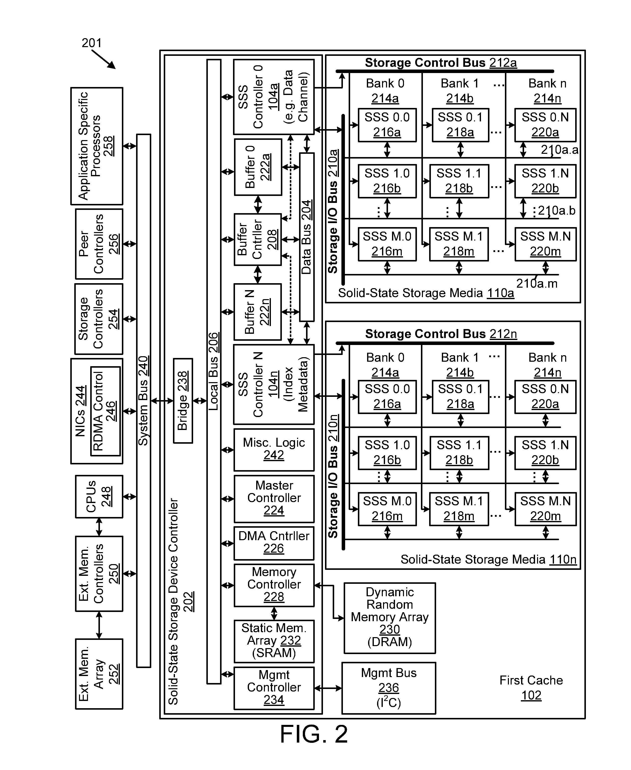
[0128]FIG. 3 is a schematic block diagram illustrating one embodiment 300 of a solid-state storage controller 104 with a write data pipeline 106 and a read data pipeline 108 in a cache 102, 112 in accordance with the present invention. The embodiment 300 includes a data bus 204, a local bus 206, and buffer control 208, which are substantially similar to those described in relation to the solid-state storage device controller 202 of FIG. 2. The write data pipeline 106 includes a packetizer 302 and an error-correcting code (“ECC”) generator 304. In other embodiments, the write data pipeline 106 includes an input buffer 306, a write synchronization buffer 308, a write program module 310, a compression module 312, an encryption module 314, a garbage collector bypass 316 (with a portion within the read data pipeline 108), a media encryption module 318, and a write buffer 320. The read data pipeline 108 includes a read synchronization buffer 328, an ECC correction module322, a depacketize...

embodiment 800

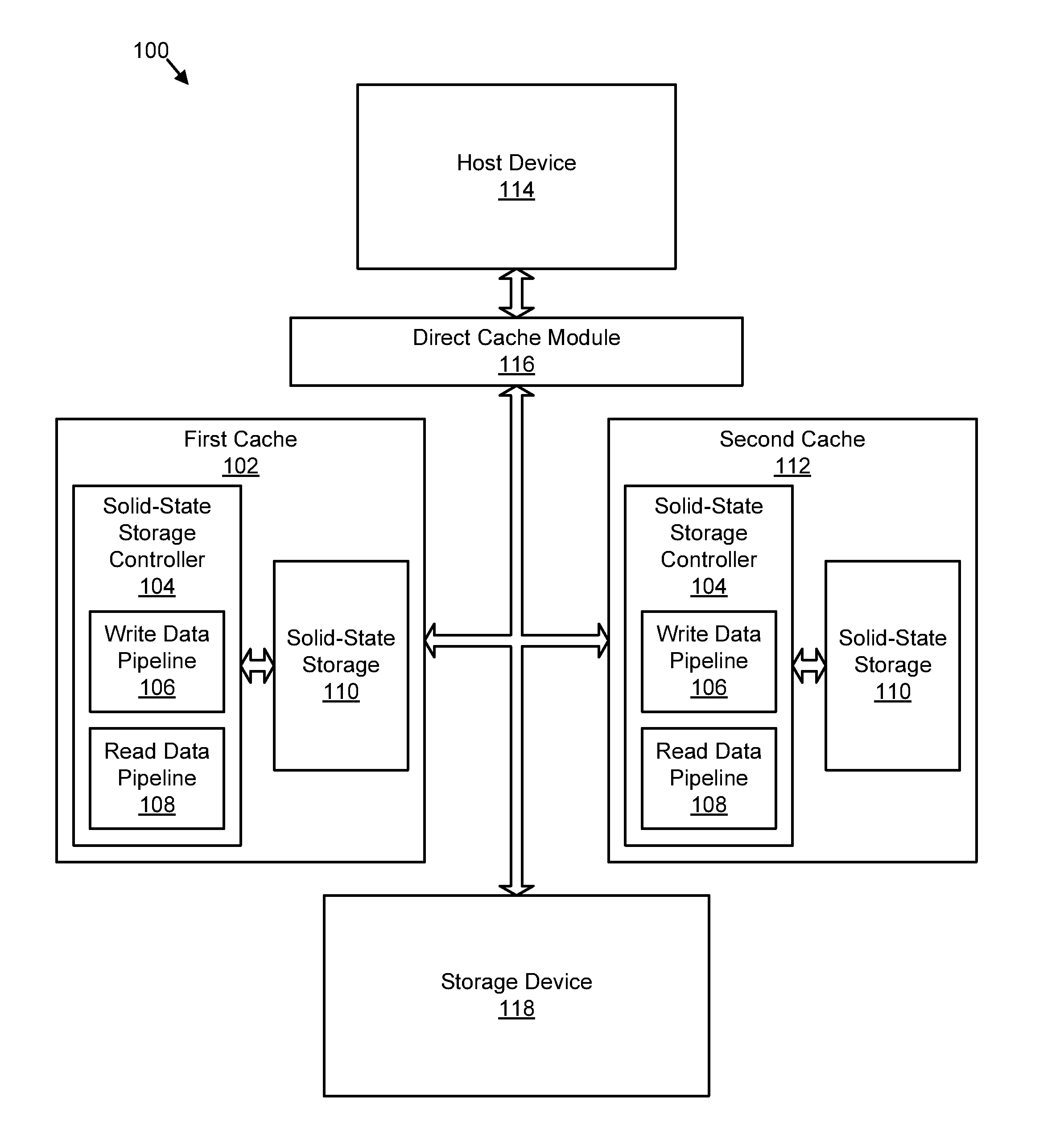
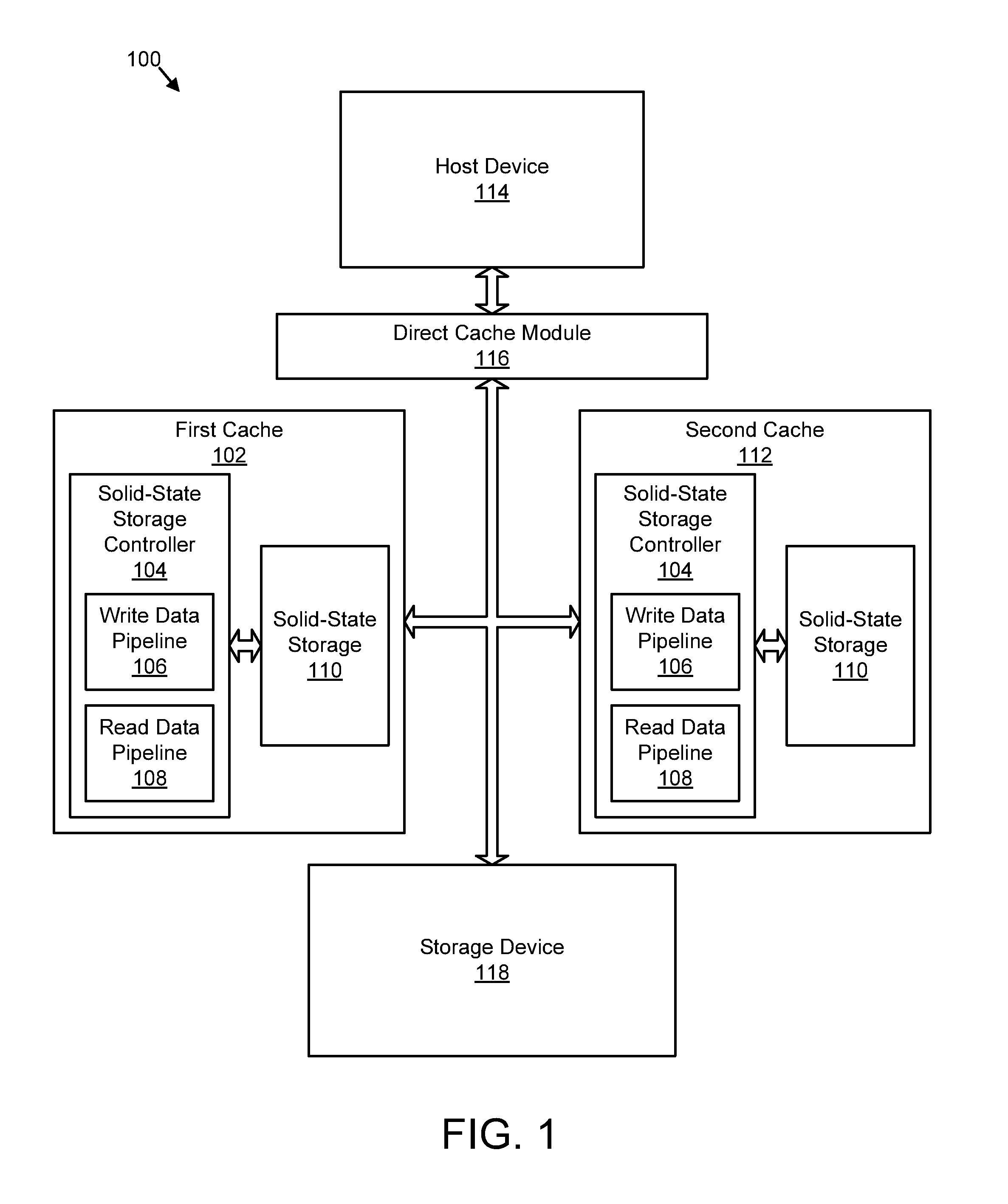
[0268]FIG. 8A depicts one embodiment 800 of the first cache 102 and the second cache 112. The depicted embodiment 800 illustrates a portion of a logical address space shared by both the first cache 102 and the second cache 112. As used herein a logical address space shared by two caches means that a given logical address may be mapped to a physical location in both caches. This means that data for a given logical address can exist in one cache or the other cache, or both caches.

[0269]The depicted embodiment 800 includes logical addresses 804a-e for the first cache 102 and the second cache 112 and data 810 associated with the logical addresses 804a-e. In the depicted embodiment 800, the logical addresses 804a-e each mirror data 810 between the first cache 102 and the second cache 112.

[0270]In the depicted embodiment 800, the first cache 102 and the second cache 112 share a logical address space that includes the set of logical addresses 804a-e. In one embodiment, physical storage cap...

embodiment 820

[0274]In the depicted embodiment 820, the cache selection module 702 selects odd logical addresses 804 for the trim module 606 to clear data 810 from the first cache 102 and selects even logical addresses 804 for the trim module 606 to clear data 810 from the second cache 112. Once the trim module 606 has cleared data 810 corresponding to one or more odd logical addresses 804 from the first cache 102 and has cleared data 810 corresponding to one or more even logical addresses 804 from the second cache 112, at least a portion of the remaining data 810 is logically striped between the first cache 102 and the second cache 112, and data 810 corresponding to consecutive logical addresses 804 is stored by different caches 102, 112. It should be noted that while the shared address space is logically striped in the depicted embodiment, those of skill in the art recognize that the media of the caches 102, 112 may not be logically striped.

[0275]Clearing the data 810 corresponding to logical a...


PUM


Abstract

An apparatus, system, and method are disclosed for redundant write caching. The apparatus, system, and method are provided with a plurality of modules including a write request module, a first cache write module, a second cache write module, and a trim module. The write request module detects a write request to store data on a storage device. The first cache write module writes data of the write request to a first cache. The second cache write module writes the data to a second cache. The trim module trims the data from one of the first cache and the second cache in response to an indicator that the storage device stores the data. The data remains available in the other of the first cache and the second cache to service read requests.

Description

CROSS-REFERENCES TO RELATED APPLICATIONS[0001]This is a continuation-in-part application of and claims priority to U.S. patent application Ser. No. 11 / 952,123 entitled “Apparatus, System, and Method for Solid-State Storage as Cache for High-Capacity, Non-Volatile Storage” and filed on Dec. 6, 2007 for David Flynn, et al., and U.S. Provisional Patent Application No. 61 / 240,573 entitled “Apparatus, System, and Method for an Improved Nonvolatile Caching Device” and filed on Sep. 8, 2009 for David Flynn, et al., which are incorporated herein by reference. U.S. patent application Ser. No. 11 / 952,123 is a continuation in part of and claims priority to U.S. Provisional Patent Application No. 60 / 873,111 filed on Dec. 6, 2006 and U.S. Provisional Patent Application No. 60 / 974,470 filed on Sep. 22, 2007, which are incorporated herein by reference.FIELD[0002]This invention relates to caching data and more particularly relates to caching write data for a data storage device.DESCRIPTION OF THE R...

Claims


Application Information

Patent Timeline
IPC IPC(8): G06F12/08
CPCG06F3/0688G06F9/52G06F11/108G06F12/0804G06F12/0866G06F13/28H04L67/1097G06F21/78G06F2211/103G06F2212/2022H04L12/40013H04L12/403H05K7/1444G06F13/4022G06F2212/222G06F2212/286
Inventor FLYNN, DAVID
Owner SANDISK TECH LLC
Why Eureka
Try Eureka