Semiconductor Power Switch

Inactive Publication Date: 2009-12-03
SCHLEIFRING & APPBAU
View PDF13 Cites 23 Cited by
  • Summary
  • Abstract
  • Description
  • Claims
  • Application Information

AI Technical Summary

Problems solved by technology

Furthermore, zero-crossing switching makes control of power flow very difficult.
This circuit offer

Method used


Image

  • Semiconductor Power Switch
  • Semiconductor Power Switch
  • Semiconductor Power Switch

Examples


Embodiment Construction

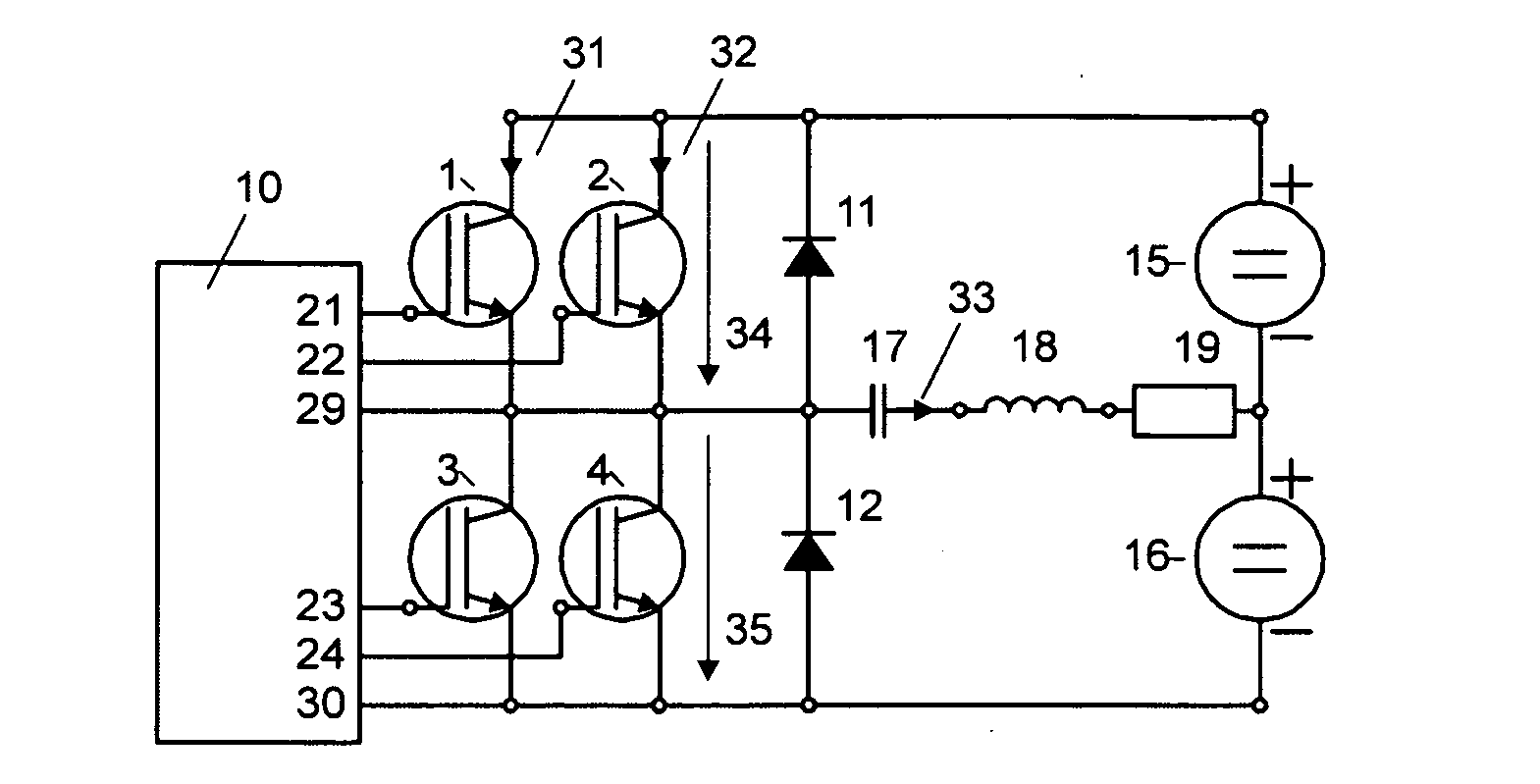
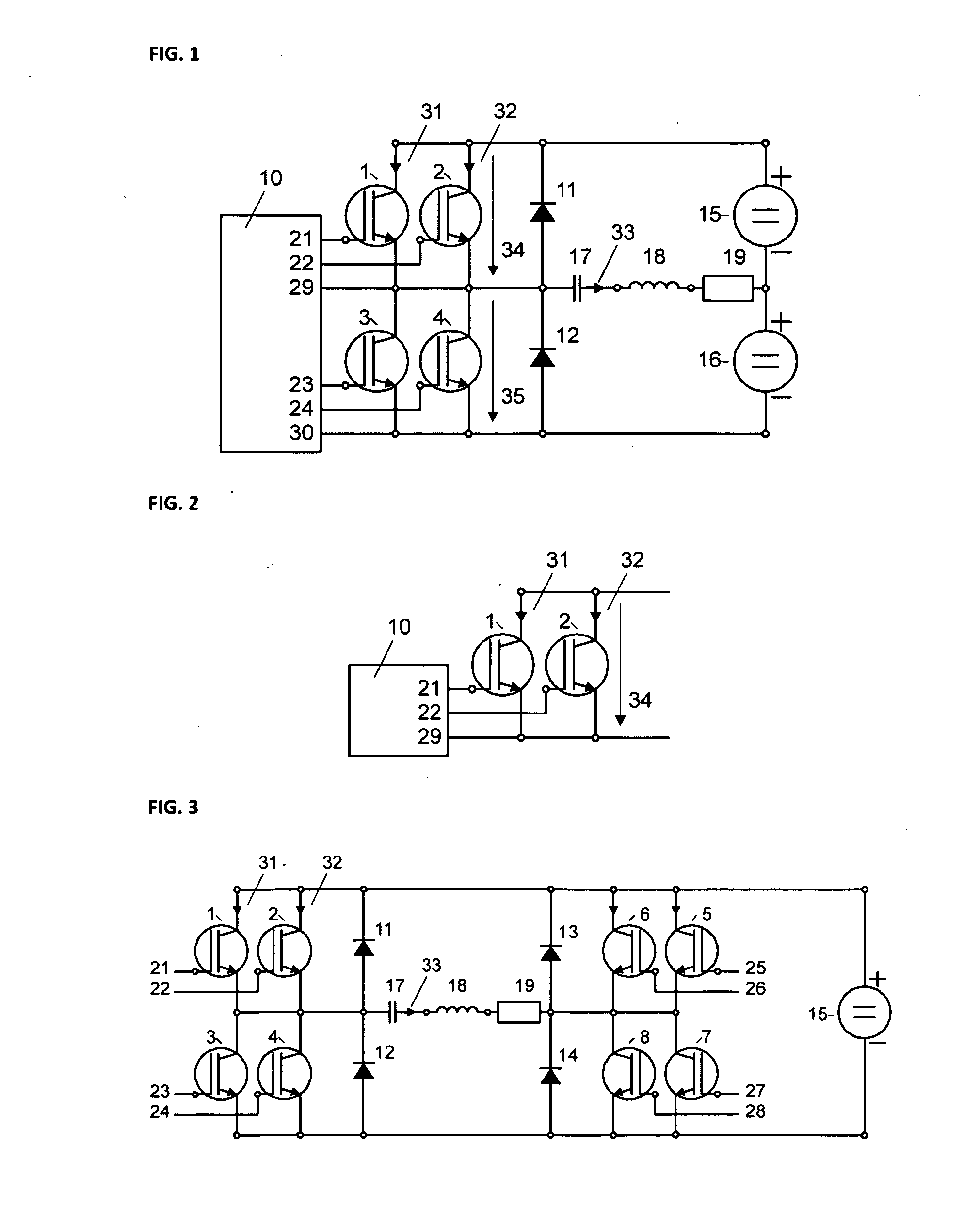
[0026]An embodiment of a power converter is disclosed in FIG. 1. The power converter shown in FIG. 1 comprises a first pair of Insulated Gate Bipolar Transistors (IGBTs) consisting of IGBT 1 and IGBT 2, and a second pair of IGBTs consisting of IGBT 3 and IGBT 4. Within each pair of IGBTs, the collectors are connected together and the emitters are connected together. A pair of serially coupled diodes 11, 12 is connected in parallel with each of the IGBT pairs, but with reversed polarity (i.e., current flow through the diodes is in an opposite direction to the current flow through the IGBT pairs).

[0027]In a preferred embodiment, each pair of IGBTs includes two different types of IGBT. For example, IGBT 1 and IGBT 3 may each be an IGBT type with a comparatively low collector-emitter on-voltage and a comparatively high turn-on or turn-off switching energy. Conversely, IGBT 2 and IGBT 4 may each be an IGBT type with a comparatively high collector-emitter on-voltage and a comparatively lo...


PUM


Abstract

A semiconductor power switch comprises at least a first IGBT and a second IGBT. The collectors of the first and second IGBTs are connected to each other, and the emitters of the first and second IGBTs are connected to each other. The first IGBT is an IGBT type with a comparatively low collector-emitter on-voltage and a comparatively high turn-on or turn-off switching energy. In contrast thereto, the second IGBT is an IGBT type with a comparatively high collector-emitter on-voltage and a comparatively low turn-on or turn-off switching energy. Both IGBTs receive gate signals from a control circuit for switching the power switch on during a first time interval and switching the power switch off during a second time interval. The control circuit is designed to supply an on-signal to the second IGBT during the whole first time interval and another on-signal to the first IGBT during only a part of the first time interval, which is less than the whole.

Description

PRIORITY CLAIM[0001]The present application claims priority to European Patent Application No. 08103832.5 filed on May 6, 2008.BACKGROUND OF THE INVENTION[0002]1. Field of the Invention[0003]The invention relates to a semiconductor power switch, based on Insulated Gate Bipolar Transistors (IGBTs), and a related power converter.[0004]2. Description of the Related Art[0005]Power converters used, for example, as DC-DC converters, are disclosed in U.S. Pat. No. 7,333,348. This patent discloses a full bridge switching circuit for driving a resonance circuit comprising a series inductance, a series capacitor, and a transformer. The full bridge switching circuit comprises Metal Oxide Semiconductor Field Effect Transistor (MOSFET) switches. For improving switching efficiency, the MOSFET switches are turned on and off during current zero-crossings of the resonance circuitry. For increasing the power level, the MOSFETs used in the switching circuit must be replaced by more powerful IGBTs. Fur...

Claims


Application Information

Patent Timeline
IPC IPC(8): H02M7/537H03K17/60
CPCH02M1/088H02M3/337H03K17/567H03K17/127H03K17/0406H02M3/33573H02M3/01
Inventor KLEMT, MICHAELKRUMME, NILS
Owner SCHLEIFRING & APPBAU
Why Eureka
Try Eureka