Switching power supply circuit

a power supply circuit and power supply technology, applied in the direction of electric variable regulation, process and machine control, instruments, etc., can solve the problems of not revealing the use of magnetic materials other than ferrite as transformer cores, leakage of magnetic flux, etc., to achieve the effect of improving the saturation characteristic, increasing the power consumption instantaneously, and improving the power supply performance to a dynamic load

Inactive Publication Date: 2009-01-15
OKI POWER TECH
View PDF9 Cites 24 Cited by
  • Summary
  • Abstract
  • Description
  • Claims
  • Application Information

AI Technical Summary

Benefits of technology

[0015]According to the present invention, in the switching power supply circuit, the saturating characteristic is improved by using the transformer or the choke coil having the core comprising the magnetic material of amorphous metal, and the suitable control operation is performed for protecting the switching element. Thus, the power supply performance to a dynamic load, in which the power consumption instantaneously increases, as a printer can be improved.

Problems solved by technology

In order to avoid this, it is necessary to form a gap in the core, but a problem of leakage of magnetic flux arises in this case.
However, JP-P3642398 or JP-P2003-284330A does not disclose that magnetic materials other than ferrite may be used as a core of the transformer.

Method used


Image

  • Switching power supply circuit
  • Switching power supply circuit
  • Switching power supply circuit

Examples


first embodiment

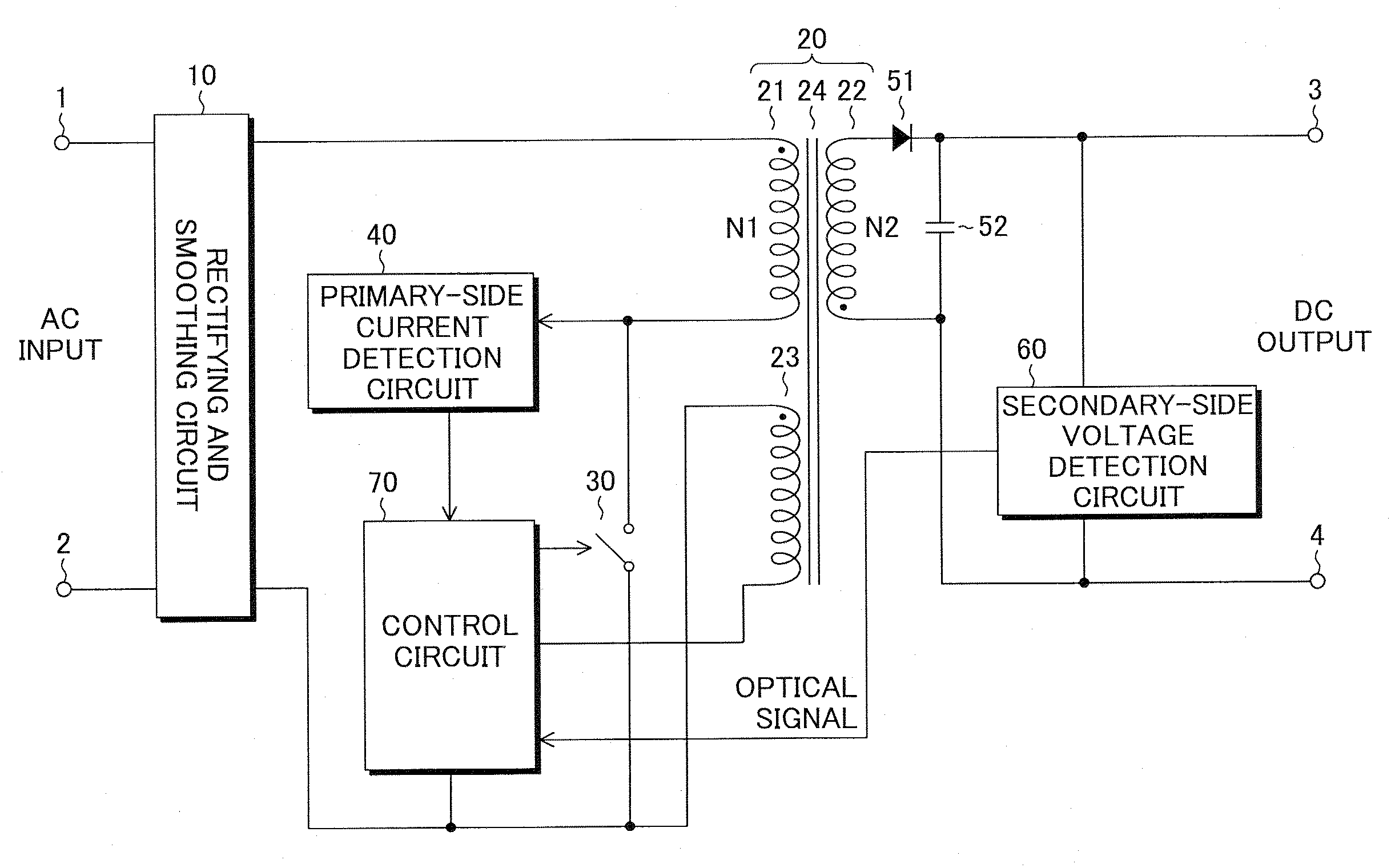
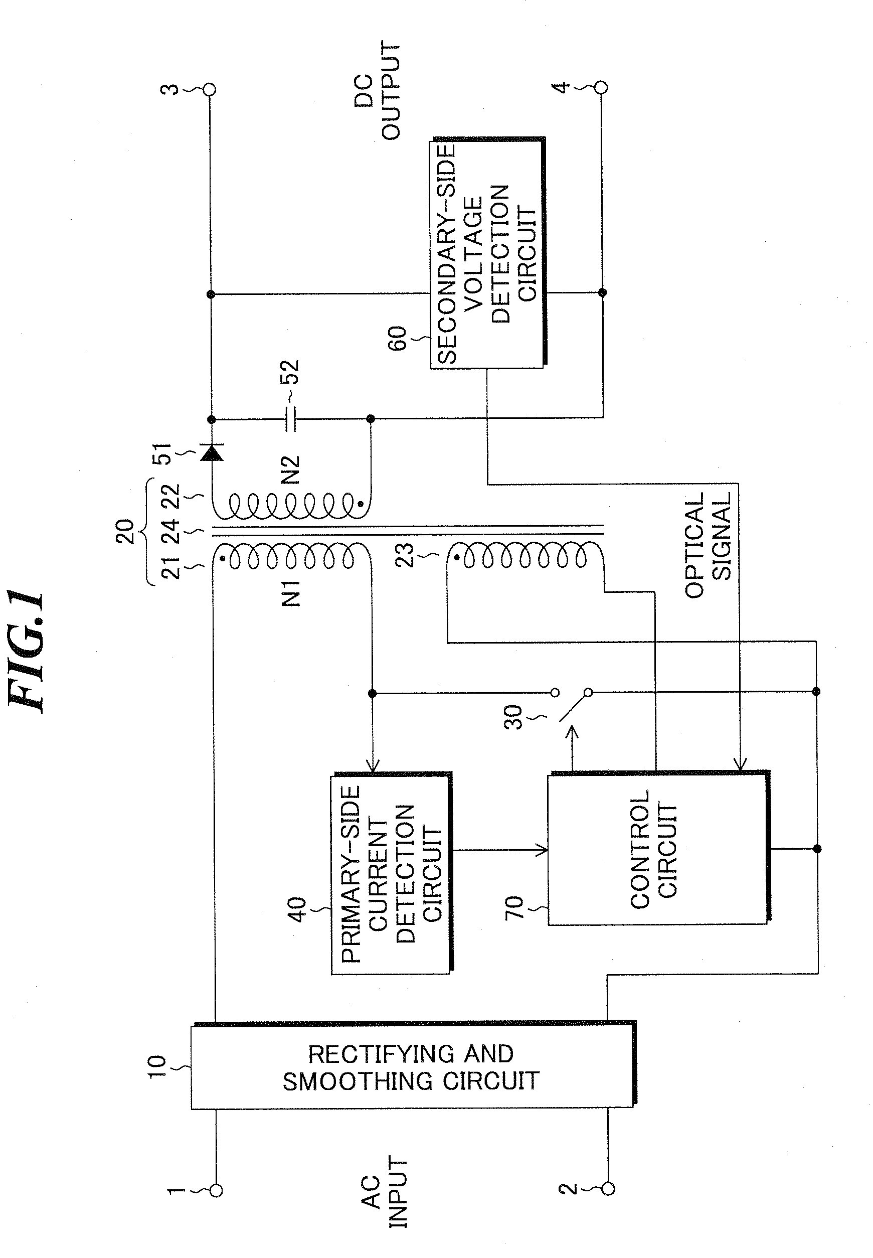
[0039]FIG. 1 shows a configuration of a switching power supply circuit according to the present invention. This switching power supply circuit has a rectifying and smoothing circuit 10 connected to input terminals 1 and 2 for an alternating-current power supply voltage, a transformer 20 for stepping up or stepping down the alternating-current voltage at the primary side and outputting it to the secondary side, a switching element 30 series-connected to a primary-side winding 21 of the transformer, for flowing current through the primary-side winding 21 of the transformer according to a pulsive drive signal, and a primary-side current detection circuit 40 for detecting the current flowing through the primary-side winding 21 of the transformer.

[0040]Further, the switching power supply circuit has a diode 51 for half-wave rectifying a voltage generated in a secondary-side winding 22 of the transformer, a capacitor 52 for smoothing the rectified voltage, a secondary-side voltage detecti...

second embodiment

[0078]FIG. 6 specifically shows the configuration of the control circuit and so on in the present invention. In the embodiment, a control circuit 90 judges whether or not the current flowing in the MOSFET 31 exceeds the rated current and generates the drive signal to be applied to the gate of the MOSFET 31 in accordance therewith. Here, the rated current refers to the magnitude of the drain current that the MOSFET can stably perform the steady operation, and determined in advance based on the AC input voltage of the switching power supply circuit, the MOSFET standard, or the like.

[0079]The control circuit 90 includes a comparator 91 and a mask signal generating circuit 92 in place of the comparator 72 as shown in FIG. 2. The comparator 91 compares the magnitude of the primary side current detected by the primary-side current detection circuit 40 with a preset voltage VP set according to the rated current, and outputs a comparison signal representing the comparison result. The mask s...

third embodiment

[0087]Next, the present invention will be explained.

[0088]FIG. 8 shows a configuration of a switching power supply circuit according to the third embodiment of the present invention. This switching power supply circuit has a rectifying and smoothing circuit 10 connected to input terminals 1 and 2 for an alternating-current power supply voltage, a transformer 20 for stepping up or stepping down the alternating-current voltage at the primary side and outputs it to the secondary side, a switching element 30 series-connected to a primary-side winding 21 of the transformer, for flowing current through the primary-side winding 21 of the transformer according to a pulsive drive signal, and a primary-side current detection circuit 100 for detecting the current flowing through the primary-side winding of the transformer 20.

[0089]Further, the switching power supply circuit has a diode 51 for half-wave rectifying a voltage generated in a secondary-side winding 22 of the transformer, a capacito...


PUM


Abstract

A switching power supply circuit uses a magnetic material that is harder to be magnetically saturated than ferrite as a core of a transformer or a choke coil and suitably protects a switching element. The circuit includes a transformer having a core made of a magnetic material of amorphous metal, a primary-side winding and a secondary-side winding. The circuit further includes a switching element for flowing current through the primary-side winding of the transformer according to a pulsive drive signal, and a primary-side current detection circuit for detecting the current flowing through the primary-side winding. The circuit further includes plural circuit elements for rectifying and smoothing a voltage generated in the secondary-side winding of the transformer to generate an output voltage, and a control circuit for generating the drive signal based on at least a detection result of the primary-side current detection circuit, and limiting a period for flowing the current in the primary-side winding.

Description

TECHNICAL FIELD[0001]The present invention relates to a switching power supply circuit to be generally used in electronic equipment, and specifically, to a switching power supply circuit for converting a commercial power supply voltage into a desired direct-current voltage by using a transformer or a choke coil.BACKGROUND ART[0002]Recent years, with the reduction in size and weight of electronic equipment, the switching power supplies, that are smaller and lighter and can efficiently output power, have been widely used. In a switching power supply, when electric insulation is necessary between the input side and the output side, a transformer is used. As a switching power supply using a transformer, a flyback switching power supply, with which a high power output voltage can be obtained, is known.[0003]In the flyback switching power supply, a primary-side winding of the transformer and a switching element are series-connected, and a direct-current voltage obtained by rectifying and ...

Claims


Application Information

Patent Timeline
Patent Type & Authority Applications(United States)
IPC IPC(8): G05F1/00
CPCH02M3/33523H02M3/155
Inventor SATO, HIDEOKOBAYASHI, TAKAHIROTAKAHASHI, HIROAKI
Owner OKI POWER TECH
Why Eureka
Try Eureka