Authentication method and framework

a technology of authentication method and authentication framework, applied in the field of authentication method and framework, can solve the problems of low transmission power, virtually undetectable transmission signal, and limiting communication distances to typically less than 10, and achieve the effect of increasing the amount of information available and flexible authentication

Inactive Publication Date: 2011-01-27
ITI SCOTLAND
View PDF4 Cites 34 Cited by
  • Summary
  • Abstract
  • Description
  • Claims
  • Application Information

AI Technical Summary

Benefits of technology

[0022]The authentication method defined in claim 1 below overcomes the disadvantages of authentication in an ad-hoc peer-to-peer network by distributing the authority across the entire network. In this way, no single entity need be trusted for the authentication process. Furthermore, more flexible authentication can be achieved using this invention than the traditional approach, due to the increased amount of information available from devices or users of the network.

Problems solved by technology

By spreading the RF energy across a large bandwidth the transmitted signal is virtually undetectable by traditional frequency selective RF technologies.
However, the low transmission power limits the communication distances to typically less than 10 to 15 meters.
However, such a flexible arrangement also raises other problems which need to be solved.
For many tasks, this can be achieved by each device independently, but some tasks cannot work this way.
This is because no peer can be trusted to operate as the central security server.
Since an ad-hoc peer-to-peer network has no single trusted server such as D, this role cannot be fulfilled.
Pre-sharing credentials in this way is appropriate for long-term usage, but not useful in an ad-hoc situation.
However, an ad-hoc peer-to-peer network by definition can have no central, trusted authentication server.

Method used


Image

  • Authentication method and framework
  • Authentication method and framework
  • Authentication method and framework

Examples


Embodiment Construction

[0031]The invention will be described hereinafter with reference to an Ultra Wideband wireless communications network. However, it will be appreciated that the invention is also applicable to other communications networks.

[0032]The invention will also be described in relation to an unauthenticated device in the form of a service-requesting device, and a secure or authenticated device in the form of a service-providing device. However, it will be appreciated that the invention is applicable to any form of device.

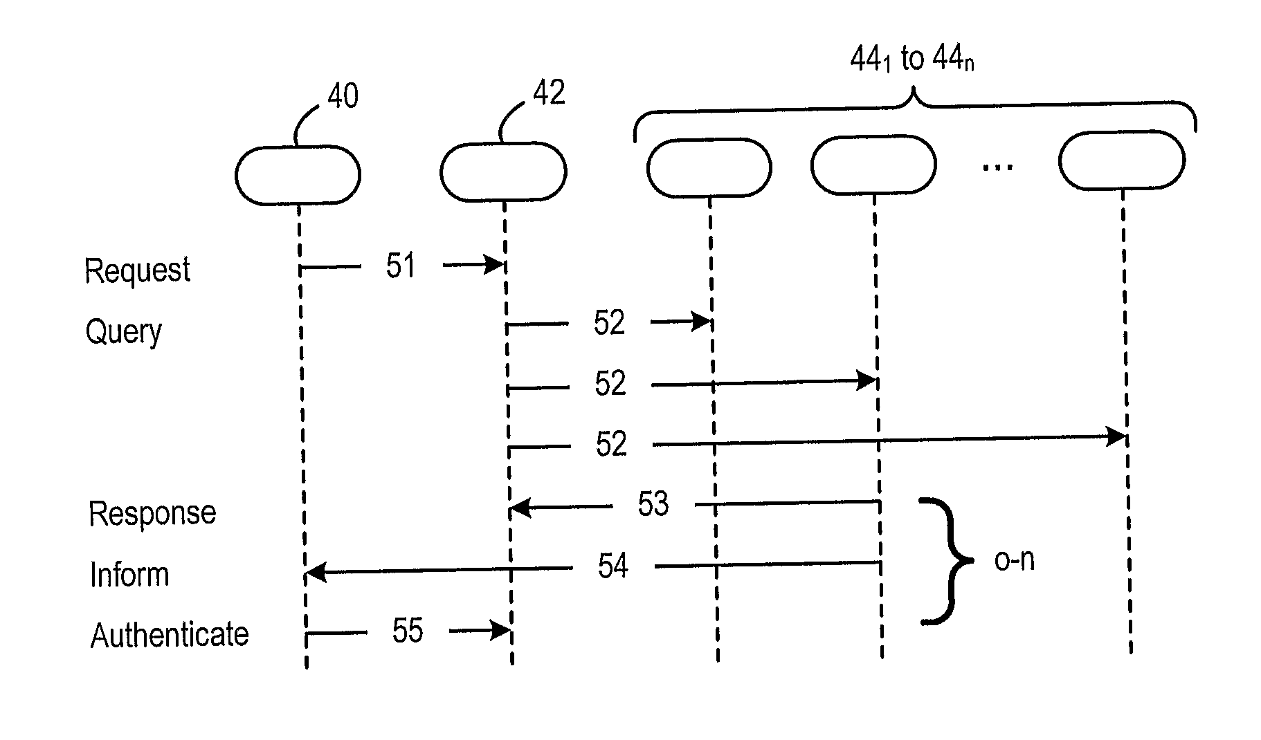
[0033]FIG. 4 shows the protocol framework for enabling an unauthenticated user 40 (for example a service-requesting device) to be authenticated with another device 42 (for example a service-providing device). According to the invention, a multi stage protocol is used to securely retrieve authentication-related information from one or more other devices 441 to 44n within the network. This allows a service-providing device 42 to verify the identity of a service-requesting devic...


PUM


Abstract

Authentication in an ad-hoc network is established between a first device (for example a service-requesting device) and a second device (for example a service-providing device) using a third device (a peer device). An authentication request is transmitted from the first device to the second device. The second device transmits a query message to at least one third device (i.e. peer device). If the peer device has previously been authenticated with the first device, the peer device sends an authentication credential, for example an authentication key, to the first and second devices. Upon receiving the authentication credential, the first device sends the authentication credential to the second device. The second device then compares the authentication credential received from the first device with the authentication credential received from the third device, and authenticates the first device with the second device if the authentication credentials match. Preferably the authentication credential from the third (peer) device to the first device is encrypted.

Description

FIELD OF THE INVENTION[0001]The invention relates to an authentication method and framework, and in particular to a peer-to-peer distributed authentication framework and method in a wireless communications network such as an Ultra Wideband communications network.BACKGROUND TO THE INVENTION[0002]Ultra-wideband is a radio technology that transmits digital data across a very wide frequency range, 3.1 to 10.6 GHz. By spreading the RF energy across a large bandwidth the transmitted signal is virtually undetectable by traditional frequency selective RF technologies. However, the low transmission power limits the communication distances to typically less than 10 to 15 meters.[0003]There are two approaches to UWB: the time-domain approach, which constructs a signal from pulse waveforms with UWB properties, and a frequency-domain modulation approach using conventional FFT-based Orthogonal Frequency Division Multiplexing (OFDM) over Multiple (frequency) Bands, giving MB-OFDM. Both UWB approac...

Claims


Application Information

Patent Timeline
IPC IPC(8): H04L29/06
CPCH04L63/0892H04L63/08H04L9/321H04W12/06H04W12/009
InventorMCDIARMID, ALISDAIRIRVINE, JAMES
OwnerITI SCOTLAND