Tool Support with Exchangeable Tool Holders and Tool Holder

a tool and tool holder technology, applied in the direction of turning machines, turret lathes, automatic/semiautomatic turning machines, etc., can solve the problems of affecting the precision of the workpiece, the relative minimum repeat accuracy of the insertion of the tool holders in one and the same receiving bore, and the change of the cutting edge of the tool, etc., to achieve simple configuration and higher positional precision

Inactive Publication Date: 2011-02-03
WTO WERKZEUG EINRICHTUNGEN
View PDF12 Cites 13 Cited by
  • Summary
  • Abstract
  • Description
  • Claims
  • Application Information

AI Technical Summary

Benefits of technology

[0013]It is an object of the present invention to provide a tool support and a tool holder that is compatible therewith that is of a si

Problems solved by technology

A disadvantage of this system is however the relatively minimal repeat accuracy for the insertion of the tool holders in one and the same receiving bore.
This relatively minimal repeat accuracy has the result that after a tool exchange, for example, because the cutting edge of a cutting chisel is worn, the position of the cutting edge of the tool will change also.
In the first scenario, the precision of the workpiece would suffer.
In the second scenario, the manufacturing costs would increase greatly.
A disadvantage of this system is the comparatively high manufacturing expenditure because into the clamping surface a groove must be milled that provides spa

Method used


Image

  • Tool Support with Exchangeable Tool Holders and Tool Holder
  • Tool Support with Exchangeable Tool Holders and Tool Holder
  • Tool Support with Exchangeable Tool Holders and Tool Holder

Examples


first embodiment

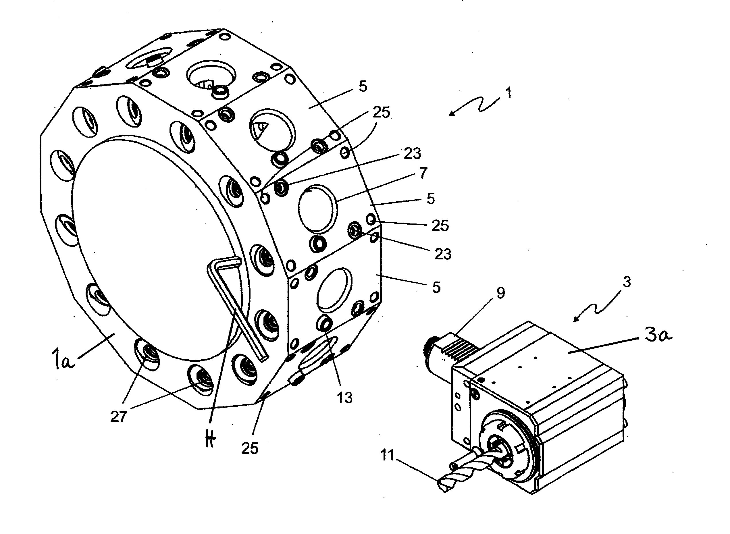
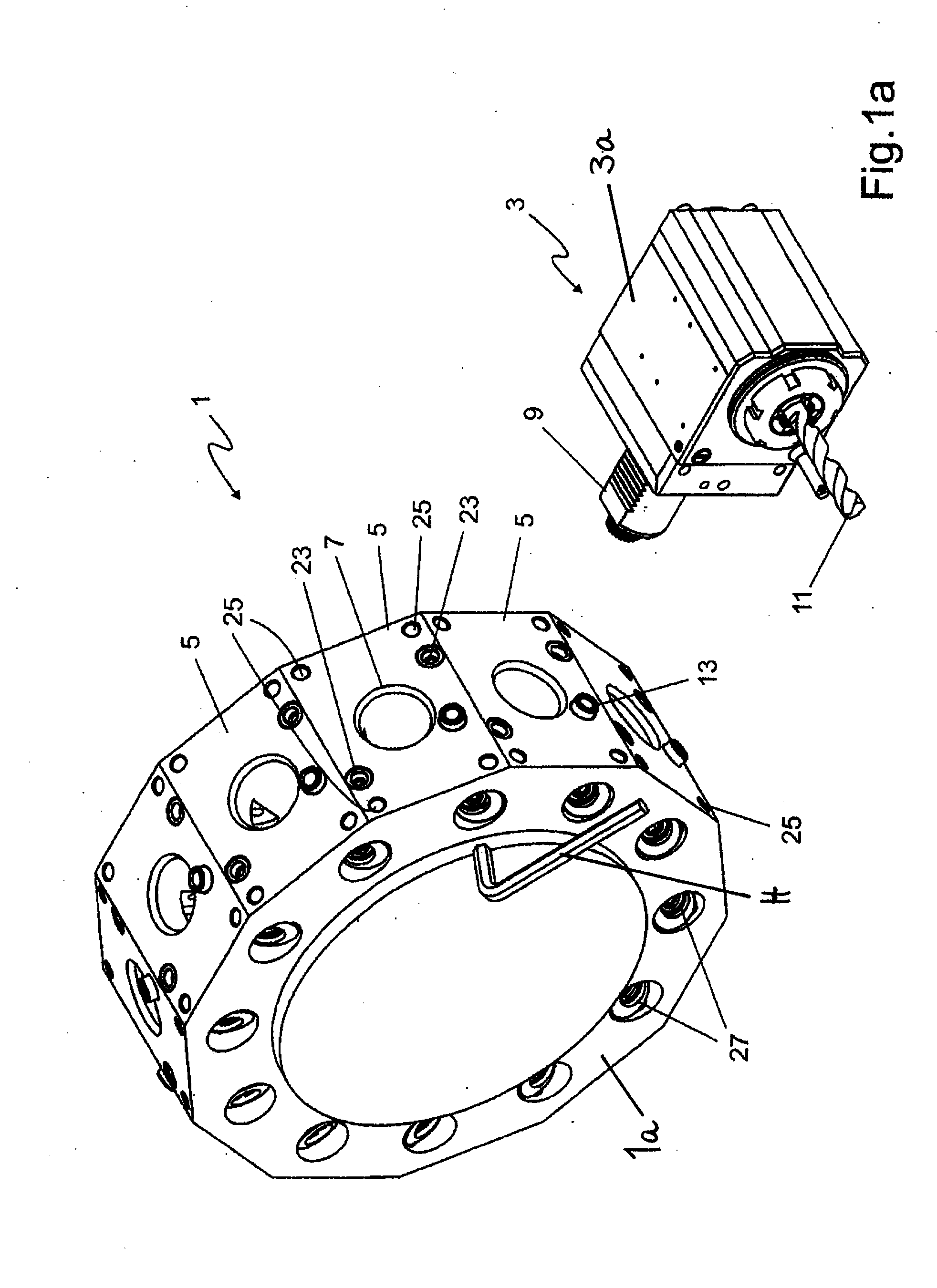
[0040]FIG. 1a shows a tool support 1 according to the present invention as well as a corresponding tool holder 3 according to the present invention in an angled embodiment illustrated in isometric view. In addition to the tool holders 3 according to the present invention the tool support 1 can also receive conventional tool holders (not illustrated) according to DIN ISO 10889-1. The tool support 1 is embodied as a so-called revolver and has a support member 1a provided at its outer circumference with a multitude of flat clamping surfaces 5. Approximately at the center of the clamping surfaces 5 a receiving bore 7 is provided that serves for receiving a cylindrical shaft 9 of the tool holder 3.

[0041]The tool holder 3 in the illustrated embodiment is provided with a spiral drill bit 11 and is inserted with the cylindrical shaft 9 into the receiving bore 7 of the tool support 1. By means of the cylindrical shaft 9 also the drive action of the spiral drill bit 11 is realized as is known...

second embodiment

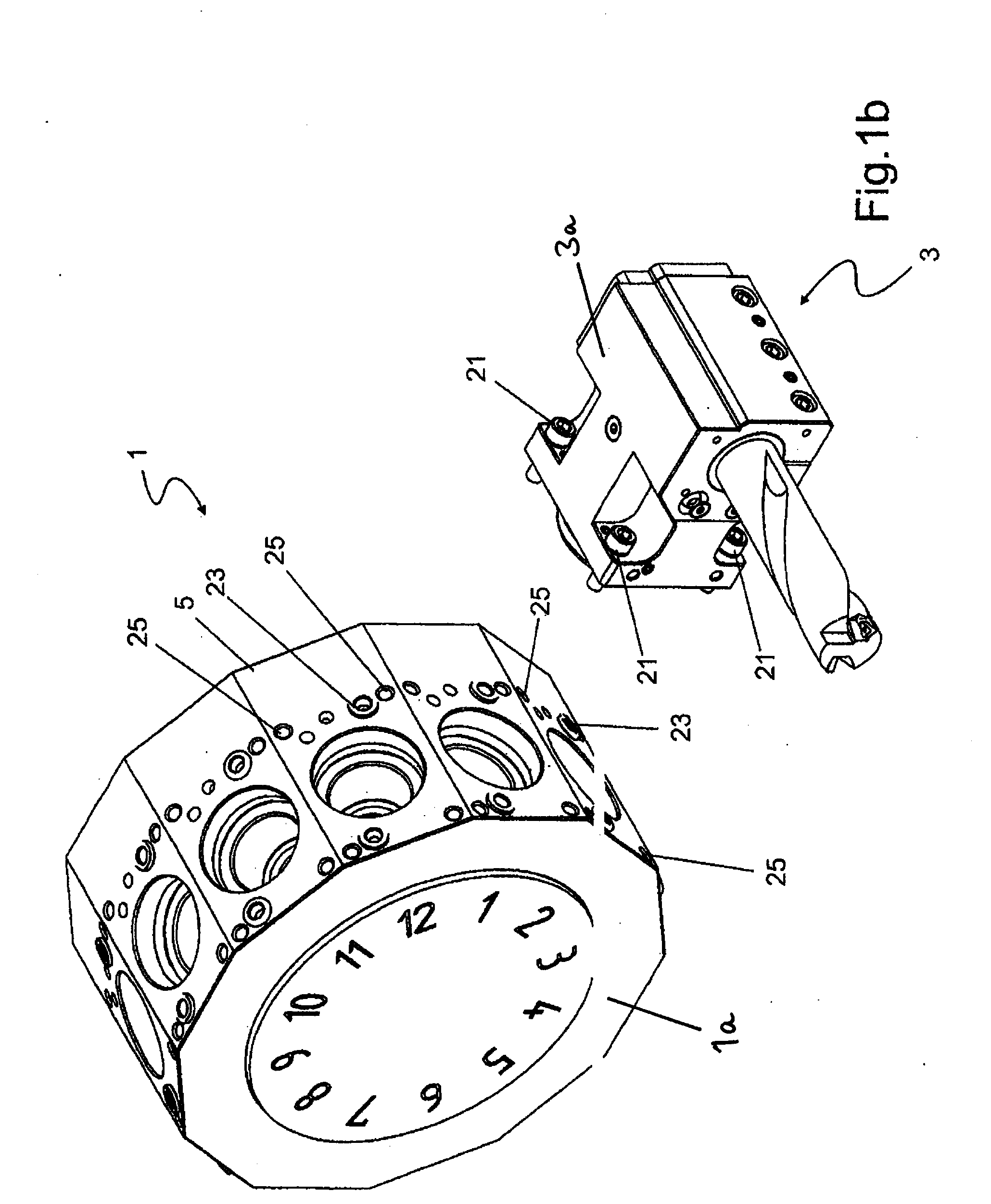
[0046]In FIG. 1b a BMT revolver 1 is illustrated that has been improved upon in accordance with the present invention. The tool holder 3 with tool holder body 3a is attached in this embodiment by means of (preferably four) fastening screws 21 screwed into the (preferably four) inner threads 25 to the revolver 1. Positioning is also realized in this embodiment by means of conical sleeves 23 and conical pins, not illustrated.

[0047]An important term for describing the quality of the interface between the tool support 1 and the tool holder 3 is the repeat accuracy for multiple insertions of a tool holder 3 into the tool support 1. The VDI interface according to DIN ISO 10889-1 achieves a repeat accuracy of approximately 0.05 mm which for many workpieces, primarily high-quality workpieces, is not sufficient and requires a time-consuming and thus expensive compensation in the control unit of the corresponding machine tool.

[0048]In FIG. 2 the tool holder 3 according to the invention illust...


PUM

PropertyMeasurementUnit
Elasticityaaaaaaaaaa

Abstract

A tool support for a machine tool has a clamping surface. A positioning device for a tool holder is provided that is positioned at the clamping surface. The positioning device has at least one conical element wherein a longitudinal axis of the conical element extends orthogonally to the clamping surface. The conical element is a conical bore or a conical pin. The tool holder is equipped with complementary conical elements so that a positive-locking, precise positioning of the tool holder relative to the receiving bore in the tool support is ensured.

Description

BACKGROUND OF THE INVENTION [0001]The invention relates to tools support with exchangeable tool holders and a tool holder for such a tool support.[0002]A multitude of tool supports is known in the art that are, for example, in the form of a so-called revolver arranged on a machine tool. These tool supports have at least one clamping surface on which an exchangeable tool holder can be positioned and attached.[0003]A very successful system of tool support and tool holder is the so-called VDI tool holder (VDI=Verein Deutscher Ingenieure; translation: Association of German Engineers) that is standardized in accordance with DIN ISO 10889-1 (DIN=Deutsches Institut für Normung; translation: German Institute for Standardization; ISO=International Organization for Standardization). This tool support is provided with a flat clamping surface in which a receiving bore is provided. Moreover, in the clamping surface a connecting bore for supply of the tool holder with a cooling lubricant may be p...

Claims


Application Information

Patent Timeline
IPC IPC(8): B23B7/04
CPCB23B29/205B23B29/24B23B29/248Y10T82/2587B23B29/20Y10T29/5155B23B2270/12
Inventor JANSEN, KARLHEINZ
Owner WTO WERKZEUG EINRICHTUNGEN
Why Eureka
Try Eureka