Method, systems and sensor for detecting humidity

a technology of humidity and sensors, applied in the direction of electrical control, instruments, machines/engines, etc., can solve the problem of erroneous ammonia readings of sensors

Inactive Publication Date: 2011-02-03
FORD GLOBAL TECH LLC
View PDF13 Cites 30 Cited by
  • Summary
  • Abstract
  • Description
  • Claims
  • Application Information

AI Technical Summary

Problems solved by technology

However, the inventors herein have recognized that depending on the ambient humidity, the ammonia reading from the sensor may be erroneous.
However, the inventors herein have also recognized that the errors due to ambient humidity manifest themselves in a predictable way across different air-fuel ratios.

Method used


Image

  • Method, systems and sensor for detecting humidity
  • Method, systems and sensor for detecting humidity
  • Method, systems and sensor for detecting humidity

Examples


Embodiment Construction

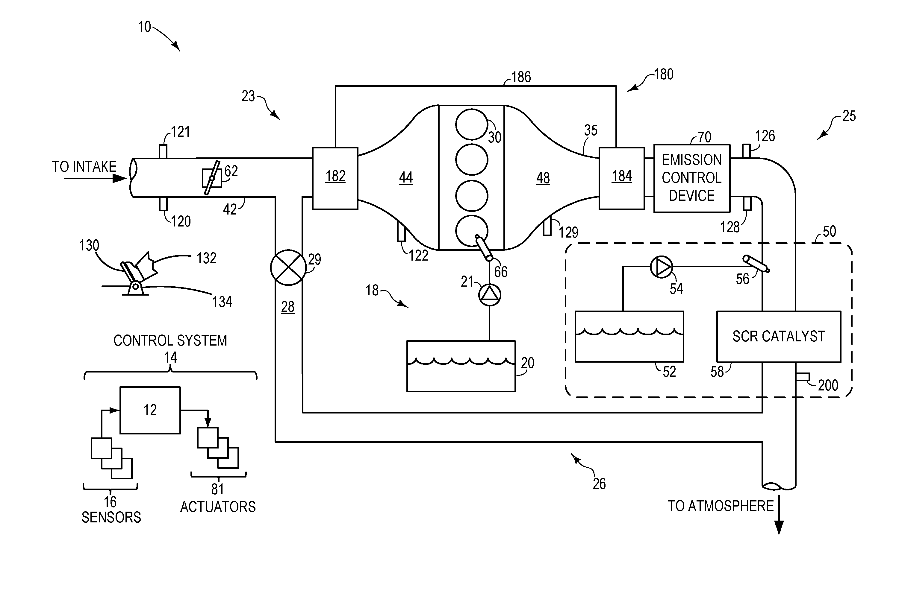
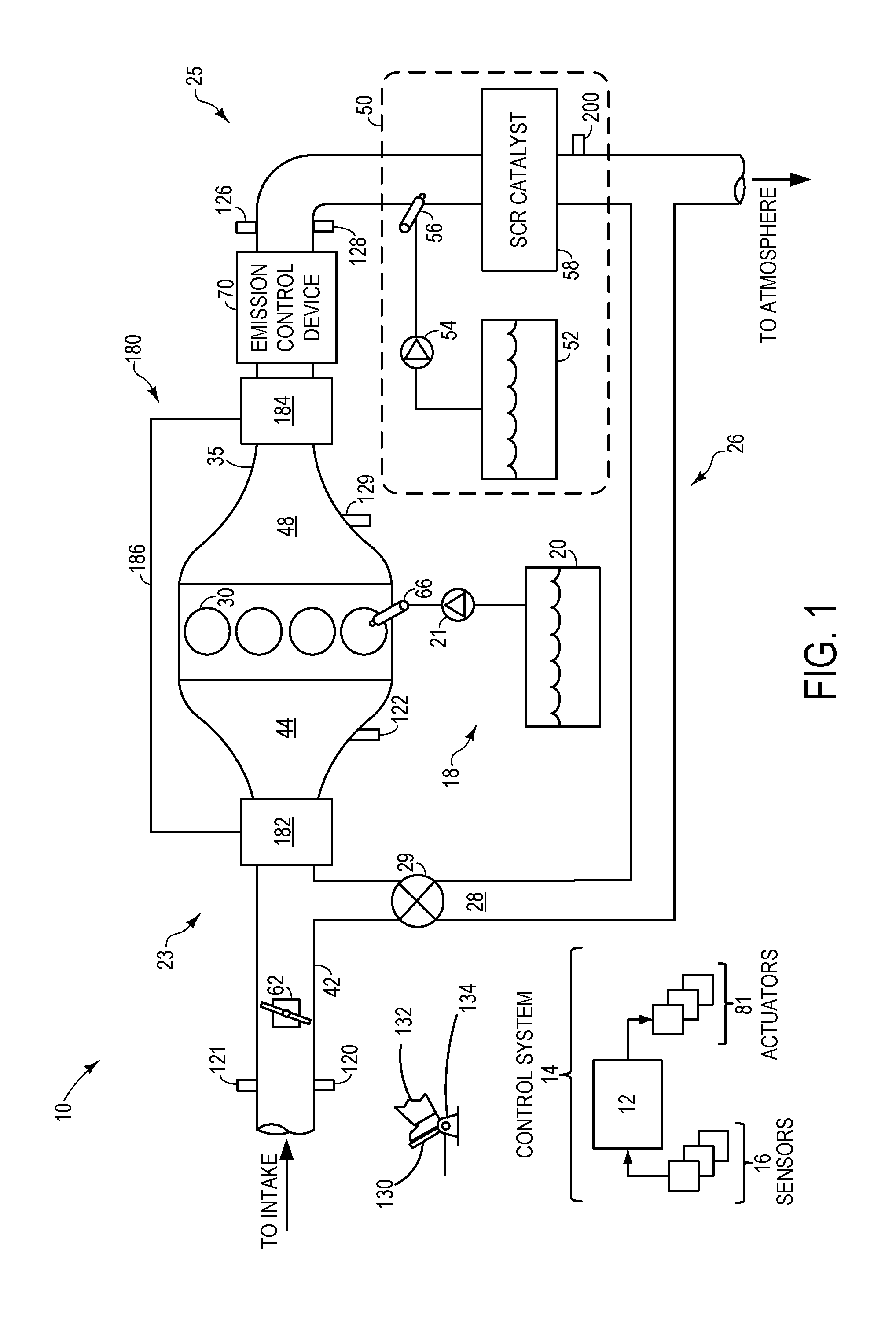
[0014]FIG. 1 shows an example diesel engine 10 including a selective catalytic reduction (SCR) system 50 with an ammonia sensor 200. Though the example presented is a diesel engine, reducing and controlling engine emissions, particularly NOx, is an important consideration in modern internal combustion engines, both spark-ignited and compression-ignited. Therefore, the systems, devices and methods described herein may be included in any exhaust system that has a reductant based SCR system.

[0015]FIG. 1 further shows engine 10 including an intake 23, an exhaust 25, a fuel system 18, an exhaust gas recirculation (EGR) system 26, and a control system 14. The engine 10 has a plurality of cylinders 30. Engine 10 may be controlled at least partially by control system 14 including controller 12, as well as by input from a vehicle operator 132 via an input device 130. In this example, input device 130 includes an accelerator pedal and a pedal position sensor 134 for generating a proportional ...


PUM


Abstract

Methods systems and device for detecting humidity in air through use of an ammonia sensor included in the exhaust of an engine, such as a diesel engine are provided. In one example, a method for an engine having an exhaust with an ammonia sensor includes adjusting an operating parameter in response to ambient humidity, the ambient humidity based on a first ammonia sensor reading at a first exhaust air-fuel-ratio and a second ammonia sensor reading at a second exhaust air-fuel-ratio.

Description

CROSS-REFERENCE TO RELATED APPLICATIONS[0001]This application claims priority from U.S. Provisional Patent Application No. 61 / 230,518, entitled “Method, Systems and Sensor for Detecting Humidity,” filed Jul. 31, 2009, the disclosure of which is hereby incorporated by reference in its entirety and for all purposes.TECHNICAL FIELD[0002]The present application relates to adjusting various operating parameters in response to ambient air humidity, the humidity identified based on an ammonia sensor included in the exhaust of an engine, such as a diesel engine.BACKGROUND AND SUMMARY[0003]Ammonia sensors may be used in exhaust emission control to maintain accurate control of injected reductant, such as injected urea. However, the inventors herein have recognized that depending on the ambient humidity, the ammonia reading from the sensor may be erroneous.[0004]However, the inventors herein have also recognized that the errors due to ambient humidity manifest themselves in a predictable way a...

Claims


Application Information

Patent Timeline
Patent Type & Authority Applications(United States)
IPC IPC(8): F02D41/00F01N3/00F01N3/04
CPCF01N3/208F01N2560/021F01N2560/025F01N2610/02F02B37/00F02D41/1408F01N13/009F02D41/1475F02D2041/1468F02D2200/0418F01N11/00Y02T10/24F02D41/1444Y02A50/20Y02T10/12
Inventor VAN NIEUWSTADT, MICHIEL J.WEBER, DAVE CHARLES
Owner FORD GLOBAL TECH LLC
Why Eureka
Try Eureka