Evaporative pre-cooler for air cooled heat exchangers

a technology of pre-cooler, which is applied in the field of evaporative coolers, can solve the problems of large air cooled heat exchangers with multiple independently staged fans, high complexity and variable air flow of evaporative pre-coolers, and monoblock pre-cooler systems cannot adapt, so as to improve the efficiency of power plants, reduce the temperature of combustion air, and enhance the effect of power plants

Inactive Publication Date: 2011-02-03
DAY MICHAEL S +3
View PDF1 Cites 33 Cited by
  • Summary
  • Abstract
  • Description
  • Claims
  • Application Information

AI Technical Summary

Benefits of technology

[0026]Another object of the present invention is to enhance efficiency of a power plant by decreasing a temperature of combustion air entering the power plant.
[0027]Another object of the present invention is to enhance efficiency of a power plant by increasing effectiveness of a heat exchanger and / or decreasing a size of a heat exchanger required for the power plant by evaporatively pre-cooling air utilized for cooling of working fluid within the heat exchanger.
[0028]Another object of the present invention is to provide an evaporative pre-cooler which is adjustable to provide a proper amount of water to air for air saturation, and without excessive water usage.
[0029]Another object of the present invention is to provide an evaporative pre-cooler which recirculates condensing portions of water and run-off water utilized thereby to minimize water consumption.
[0030]Another object of the present invention is to provide an evaporative pre-cooler which minimizes scale buildup within the pre-cooler system itself and minimizes scale buildup for downstream equipment.
[0031]Another object of the present invention is to provide an evaporative pre-cooler which is modular in form to be deployable in a scalable fashion with smaller and larger mechanical equipment which receives air therein.

Problems solved by technology

Numerous problems exist in implementing such evaporative pre-coolers with such heat exchangers or other air receiving equipment.
For instance, large air cooled heat exchangers with multiple independently staged fans have highly complex and variable air flow.
Existing monoblock pre-cooler systems cannot adapt to this air flow rate variability, and so either supply too much water or too little.
Supplying too much water wastes water and can damage a heat exchanger or turbine.
In such cases liquid water is entrained into the air stream where it can do damage either through direct impingement or through the deposition of dissolved solids on the heat exchanger.
Providing too little water flow results in lower efficiency gains than could be achieved using the correct amount of water.
Because such fine mist water spray requires substantially constant high pressure for effective operation, merely throttling water flow through a flow rate control valve to provide variable water flow rates results in degradation of performance of the nebulizer and less fine spray, thus providing an incomplete solution.
This strategy presents a challenge to high pressure flash evaporative systems.
This portion of time in each cycle which is spent at sub-optimal pressure degrades high pressure nozzle performance.
Other types of pre-coolers which utilize saturated water pads and flow air through those pads are less than desirable for a variety of reasons.
For instance, they have a tendency to shed large amounts of water into the air flow which then can damage downstream equipment.
Furthermore, large amounts of water require recycling, and such recycling systems which recirculate a bulk of the water therein have a tendency to concentrate dissolved solids during recycling, ultimately leading to scale buildup and performance degradation.
While chemical treatment (and / or periodic or continuous water discharge) can reduce scale formation and biological growth, such chemical treatments (and / or discharge) can present a negative ecological impact.
This impingement can result in additional scale buildup for downstream equipment and also potentially damage to downstream equipment through direct impingement.
These designs are problematic because the temperature response signal becomes corrupted by heat rejected by the heat exchanger of the upgraded unit.
However, the air entering the heat exchanger might already be saturated, and such a feedback signal will inappropriately add water flow beyond a point of saturation of the air with associated negative consequences.
Other sensors for evaporative coolers may try to sense ambient psychrometric conditions but fail to measure air flow to the device.
Without knowing both airflow and psychrometric conditions, it is not possible to calculate or deliver an appropriate mass of water for a given air stream.

Method used


Image

  • Evaporative pre-cooler for air cooled heat exchangers
  • Evaporative pre-cooler for air cooled heat exchangers
  • Evaporative pre-cooler for air cooled heat exchangers

Examples


Embodiment Construction

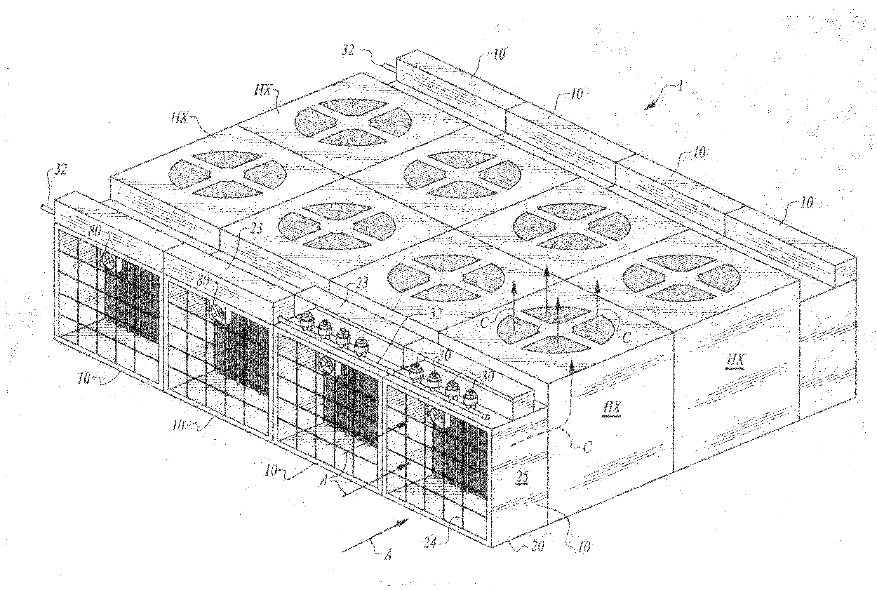
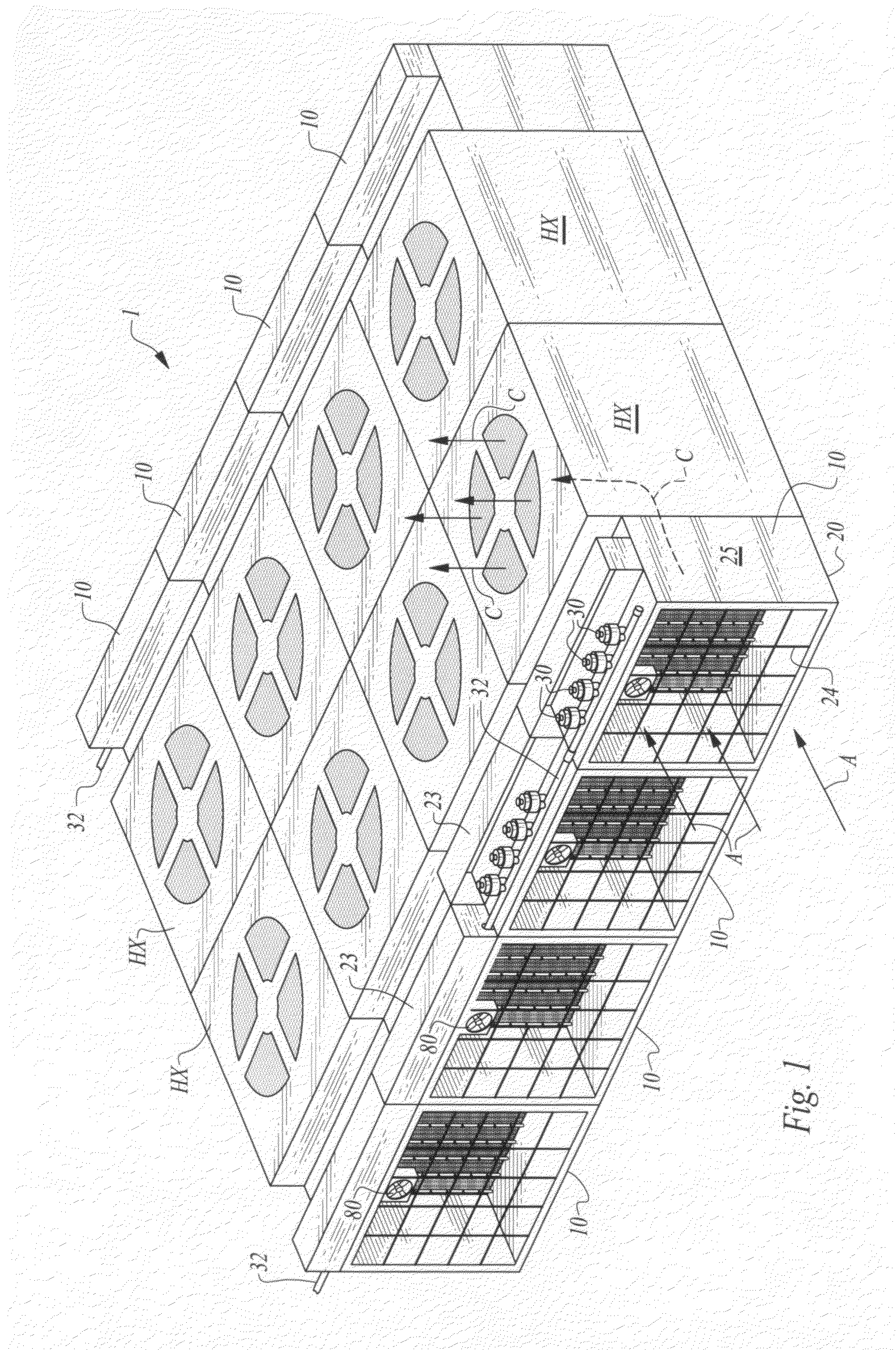
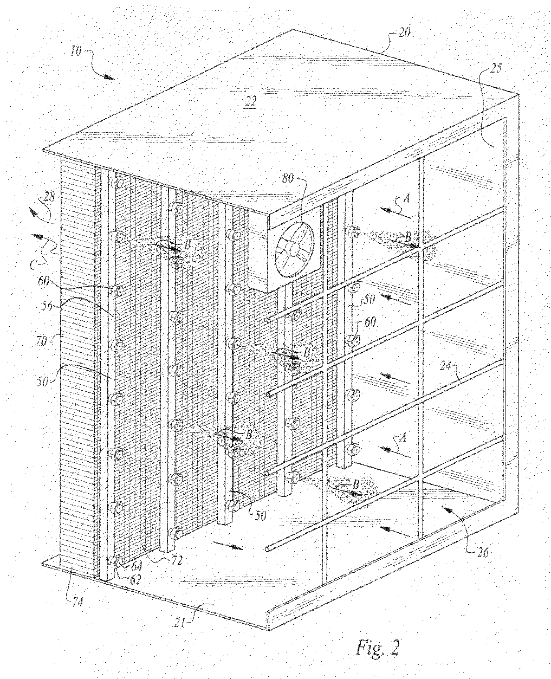
[0041]Referring to the drawings, wherein like reference numerals represent like parts throughout the various drawing figures, reference numeral 10 is directed to a pre-cooler cell (FIGS. 1 and 2) for use alone or together adjacent a heat exchanger HX or system 1 of multiple heat exchangers HX to pre-cool air (arrow A of FIG. 1) entering the heat exchangers HX. The pre-cooler 10 evaporates water into the air to reduce a temperature of the air and increase a mass of the air for enhanced effectiveness of the heat exchanger HX. The cells 10 are configured to have a precise and highly adjustable water flow rate while maintaining a fine spray of water for consistent evaporative effectiveness, maximizing air temperature reduction while avoiding water droplet carryover downstream.

[0042]In essence, and with particular reference to FIG. 2, basic details of the pre-cooler cell 10 of this invention are described, according to a most preferred embodiment. The cell 10 includes a housing 20 as a p...


PUM


Abstract

The pre-cooler includes one or more cells which are oriented about an air stream to be cooled. A housing defines a perimeter of the cell with an inlet and outlet for air passing therethrough. Water outlet nozzles within the housing are preferably supported upon bars which orient the nozzles facing in a direction counter to flow of air through the housing. Each nozzle is coupled to a separate stage with multiple stages of nozzles coupled to separate valves. A controller opens or closes different valves. The controller measures ambient humidity and temperature conditions as well as air flow rates to calculate the amount of water to be added to the air and then opens appropriate numbers of stages of valves so that an appropriate number of nozzles spray water into the air to saturate the air. Flow rate control is thus provided without pressure variations, for optimal nozzle performance.

Description

CROSS-REFERENCE TO RELATED APPLICATIONS[0001]This application claims benefit under Title 35, United States Code §119(e) of U.S. Provisional Application No. 61 / 273,008 filed on Jul. 29, 2009.FIELD OF THE INVENTION[0002]The following invention relates to evaporative coolers which add water to unsaturated air to cause a temperature of the air to be reduced. More particularly, this invention relates to evaporative pre-coolers for use upstream of an inlet air stream of a heat exchanger or other air receiving mechanical equipment, such as a gas turbine, to improve the thermodynamic performance and / or heat transfer effectiveness of the equipment.BACKGROUND OF THE INVENTION[0003]The efficiency of both air cooled heat exchangers and gas combustion turbines, as well as other mechanical equipment increases as air temperature decreases. Furthermore, such equipment also generally increases in efficiency as the mass of the air increases, such as high or humidity air versus lower humidity air. Wat...

Claims


Application Information

Patent Timeline
Patent Type & Authority Applications(United States)
IPC IPC(8): F25D17/06F24F3/14F28D5/00F24F11/04F28F13/12
CPCF24F5/0035F24F6/14Y02B30/545F28C3/08F28B1/06Y02B30/54
Inventor DAY, MICHAEL S.WYLIE, CALVIN R.PENROD, ROBERT D.BETTENCOURT, MICHAEL
Owner DAY MICHAEL S
Why Eureka
Try Eureka