

Environment sensor
a sensor and environment technology, applied in the field of environmental sensors, can solve the problems of low response speed in humidity measurement and the inability of conventional humidity sensors to set printing conditions, and achieve the effect of high response speed
- Summary
- Abstract
- Description
- Claims
- Application Information
AI Technical Summary
Benefits of technology
Problems solved by technology
Method used
Image

Examples
first embodiment
[0032] (First Embodiment)
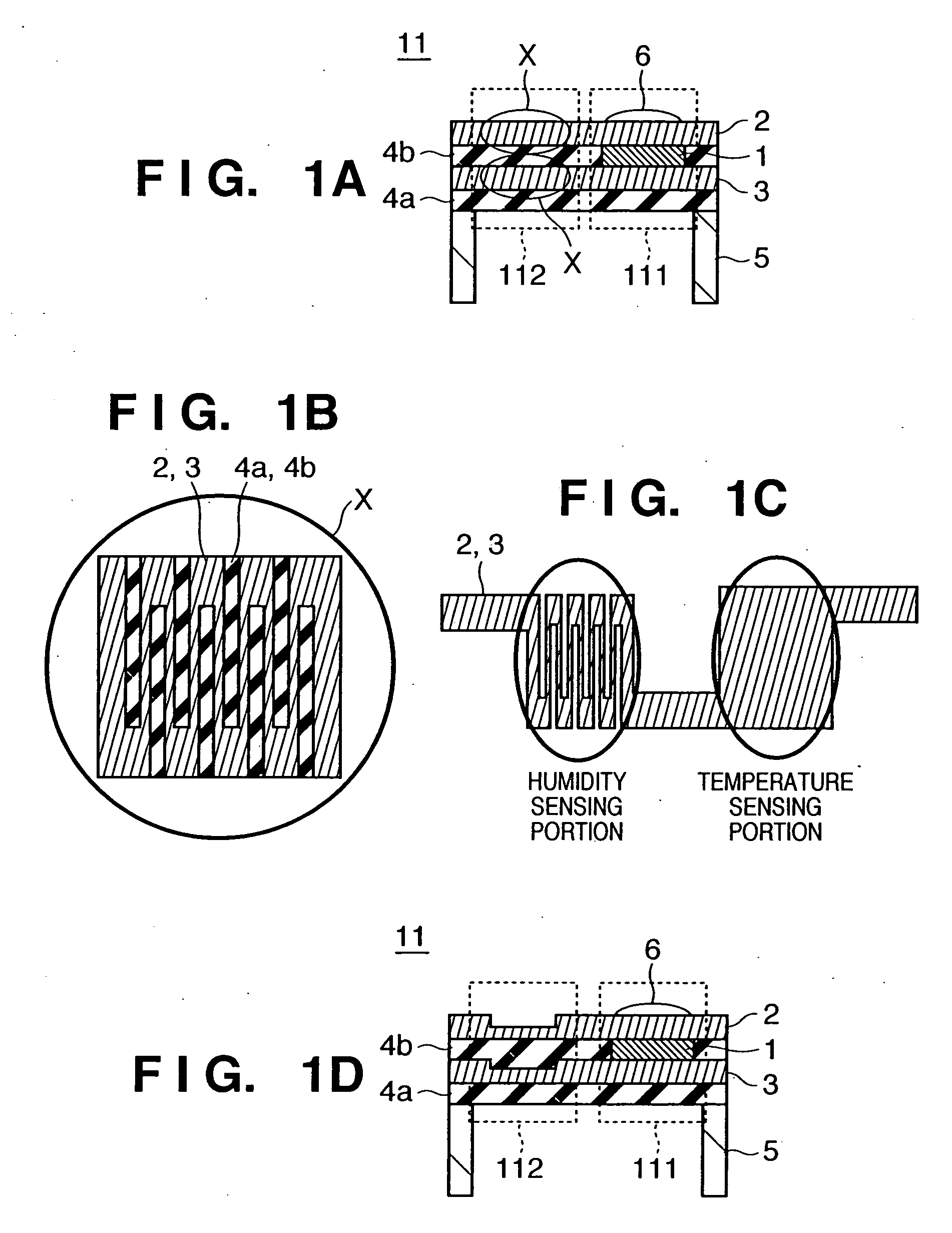
[0033]FIGS. 1A to 1D illustrate an outline of the arrangement of an environment sensor according to the first embodiment of the present invention. FIG. 1A is a schematic sectional view of the environment sensor. FIG. 1B is a schematic enlarged plan view of electrodes in a humidity sensing region X of the environment sensor. Note that FIG. 1B is not a view obtained by directly enlarging the section of the circle X in FIG. 1A, but a view obtained by enlarging a plan view of the circle X. FIG. 1C is a schematic plan view of electrodes of the environment sensor shown in FIG. 1A. FIG. 1D is a schematic sectional view of another environment sensor according to the first embodiment. Although FIGS. 1A to 1D illustrate only portions of the sensor, the overall shape of the sensor is a substantially rectangular shape. Since this shape is, of course, merely an example, the present invention is not limited to this shape.
[0034] An environment sensor 11 according to this ...
second embodiment
[0066] (Second Embodiment)
[0067]FIGS. 5A and 5B illustrate an outline of the arrangement of an environment sensor according to the second embodiment of the present invention. FIG. 5A is a schematic sectional view of the environment sensor. FIG. 5B is an enlarged plan view of electrodes in a humidity sensing region of the environment sensor shown in FIG. 5A. That is, the sensor is viewed from the side in FIG. 5A, and viewed from the above in FIG. 5B.
[0068] As shown in FIG. 5A, an environment sensor 21 according to this embodiment includes a temperature sensing portion 211 and humidity sensing portion 212. Reference numerals 1a and 1b denote metal oxide layers; 2, an upper electrode; 3, a lower electrode; 4a and 4b, insulator layers; 5, a substrate; and 6, an infrared transmitting material. The metal oxide layers 1a and 1b are made of a ferroelectric or pyroelectric. Although the infrared transmitting material 6 is so formed as to have a curved surface in FIG. 5A, the shape is not pa...
third embodiment
[0088] (Third Embodiment)
[0089] The third embodiment of the present invention relates to an environment measurement apparatus including the environment sensor according to the present invention.
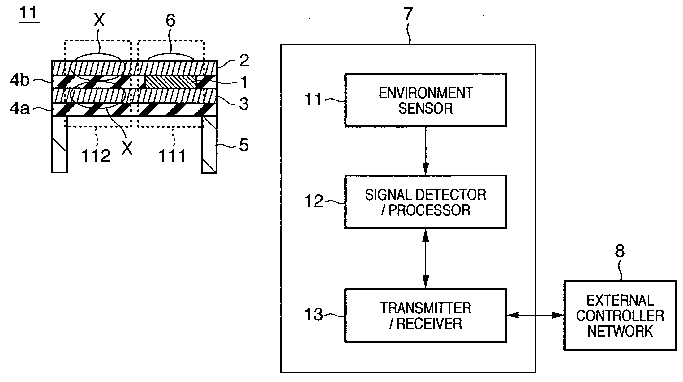
[0090]FIG. 8 is a block diagram showing the environment measurement apparatus according to the third embodiment of the present invention.
[0091] An environment measurement apparatus 7 includes an environment sensor 11 according to the present invention which measures the temperature and humidity, a signal detector / processor 12 which detects and processes an output electrical signal from the environment sensor 11, and a transmitter / receiver 13 having functions of transmitting a signal from the signal detector / processor 12 to an external controller 8, and transmitting instructions from the external controller 8 to the signal detector / processor 12.
[0092] The signal detector / processor 12 measures the electrical resistances and electric currents of the electrodes, and the capacitance, resistance...
PUM
| Property | Measurement | Unit |
|---|---|---|
| thickness | aaaaa | aaaaa |
| thicknesses | aaaaa | aaaaa |
| thicknesses | aaaaa | aaaaa |
Abstract
Description
Claims
Application Information