Methods and systems for humidity detection via an exhaust gas sensor

a technology of humidity measurement and exhaust gas, which is applied in the direction of electric control, combustion engines, machines/engines, etc., can solve the problems of affecting the efficiency of the engine, and consuming a large amount of pcv, so as to reduce the impact of pcv on humidity estimation, reduce the loss of pumping, and improve engine efficiency

Active Publication Date: 2014-07-24
FORD GLOBAL TECH LLC
View PDF1 Cites 32 Cited by
  • Summary
  • Abstract
  • Description
  • Claims
  • Application Information

AI Technical Summary

Benefits of technology

[0004]The inventors herein have recognized the above issue and have devised an approach to at least partially address it. Thus, a method for an engine system which includes an exhaust gas sensor is disclosed. In one example, the method comprises: selectively deactivating a first group of cylinders while maintaining a second group of cylinders active, modulating a reference voltage of a first exhaust gas sensor coupled downstream of the first group of cylinders, inferring an ambient humidity based on sensor output generated by the first sensor responsive to the modulating; and adjusting an engine operating parameter of the second group of cylinders based on the inferred ambient humidity. In this way, the humidity estimation may be performed in the deactivated bank of a variable displacement engine, reducing the need to wait for a DFSO condition.
[0005]As an example, during low load conditions, cylinders on a first engine bank may be selectively deactivated while cylinders on a second engine bank remain active. This reduces pumping losses and improves engine efficiency. While fuel and spark to the first engine bank is deactivated, a first exhaust gas oxygen sensor coupled downstream of the first engine bank (but not the second engine bank) may be modulated for ambient humidity detection. Specifically, each of a first, lower voltage (e.g., 450 mV) and a second, higher voltage (e.g., 1080 mV) may be alternately applied on the sensor and a sensor output each voltage (e.g., a pumping current at each voltage) may be noted. Based on a difference between the first and second pumping currents, an ambient humidity may be estimated. Concurrently, while the second engine bank is active, a second exhaust gas oxygen sensor coupled downstream of the second engine bank (but not the second engine bank) may be modulated for fuel ethanol content detection and / or exhaust air-fuel ratio determination. Specifically, during a first condition, only the first voltage may be applied on the second sensor and an air-fuel ratio may be estimated based on a first pumping current output by the sensor. Then, during a second condition, each of the first and second voltage may be alternately applied on the second sensor and fuel ethanol content may be estimated based on a difference between the first and second pumping currents output by the sensor at the first and second voltages, respectively. An engine operating parameter of the active bank (e.g., fuel injection amount, spark timing, EGR amount, etc.) may then be adjusted based on the ambient humidity estimated on the inactive bank, as well as the air-fuel ratio and ethanol content estimated on the active bank.
[0006]In this way, by modulating the reference voltage and determining the change in pumping current at an exhaust gas oxygen sensor coupled to a selectively deactivated engine bank, the need to wait for a DFSO condition is reduced while also nullifying the effect of any changing air fuel ratio. By not waiting for a DFSO condition, the PCV impact on humidity estimation is also reduced. Further, the ambient humidity may be determined in a shorter amount of time, as the exhaust air fuel ratio does not have to be stable before an accurate indication of ambient humidity may be determined. Further still, by concurrently modulating the reference voltage and determining the change in pumping current at an exhaust gas oxygen sensor coupled to the active engine bank, fuel ethanol content estimation and air-fuel ratio estimation can be performed at the same time as ambient humidity estimation.

Problems solved by technology

However, the need to wait for a DFSO condition can delay the humidity measurement.
In addition, it may take a long time for the exhaust flow to be devoid of hydrocarbons during the engine non-fueling conditions.
Further, during the DFSO, when an intake throttle is closed, large manifold vacuum is generated which can lead to ingestion of a large amount of PCV.
The ingested PCV can impact the sensor output and confound the humidity measurement.

Method used


Image

  • Methods and systems for humidity detection via an exhaust gas sensor
  • Methods and systems for humidity detection via an exhaust gas sensor
  • Methods and systems for humidity detection via an exhaust gas sensor

Examples


Embodiment Construction

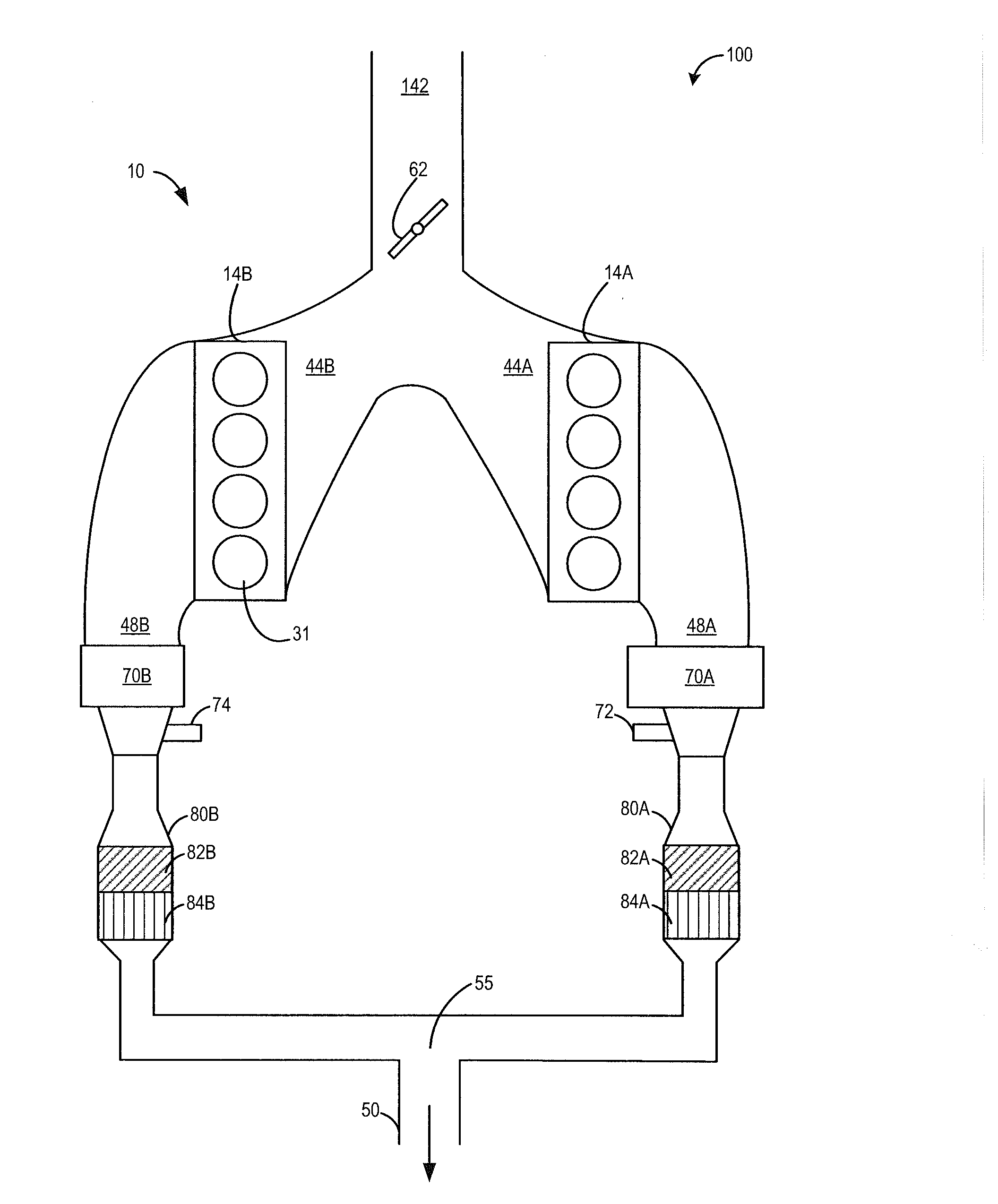
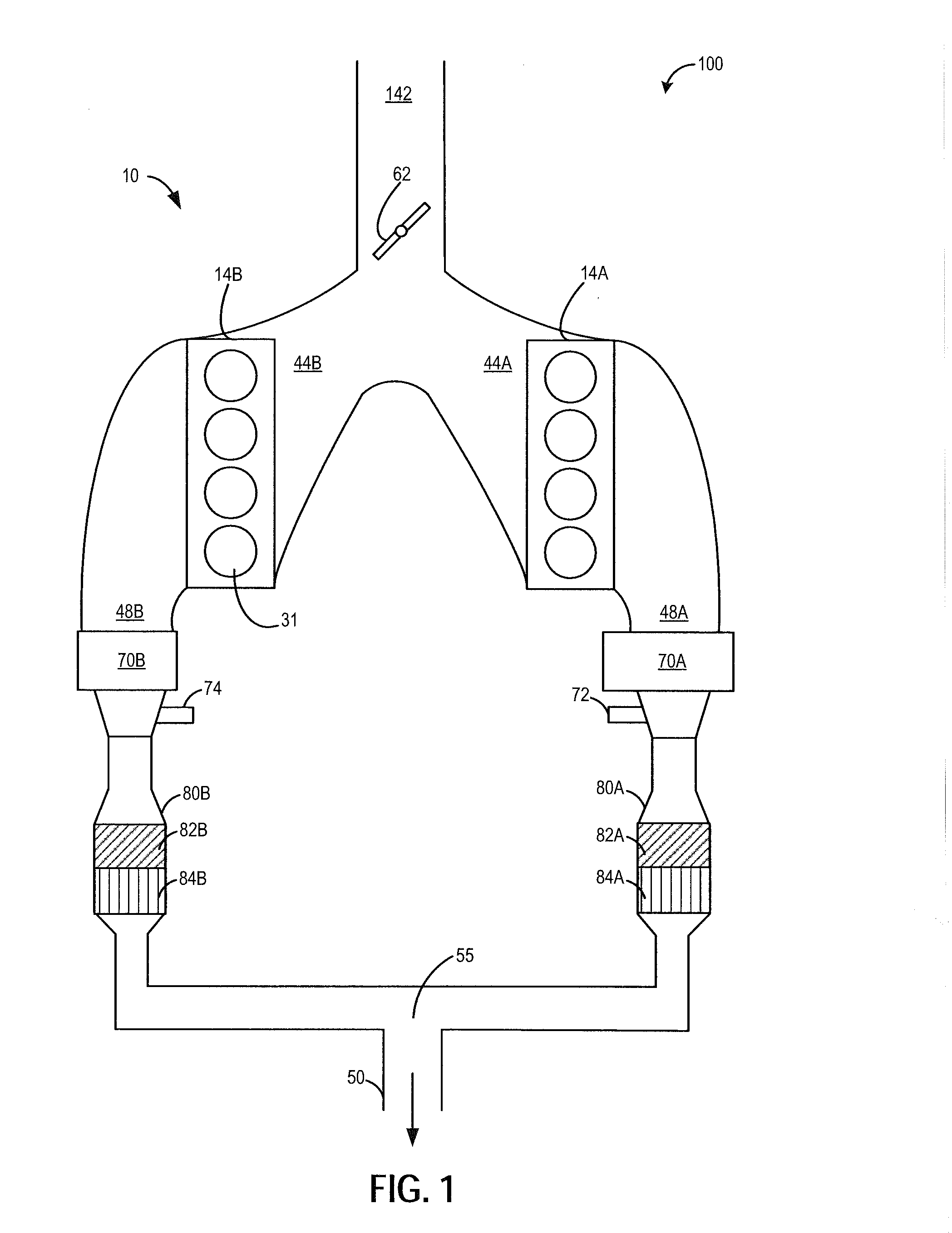
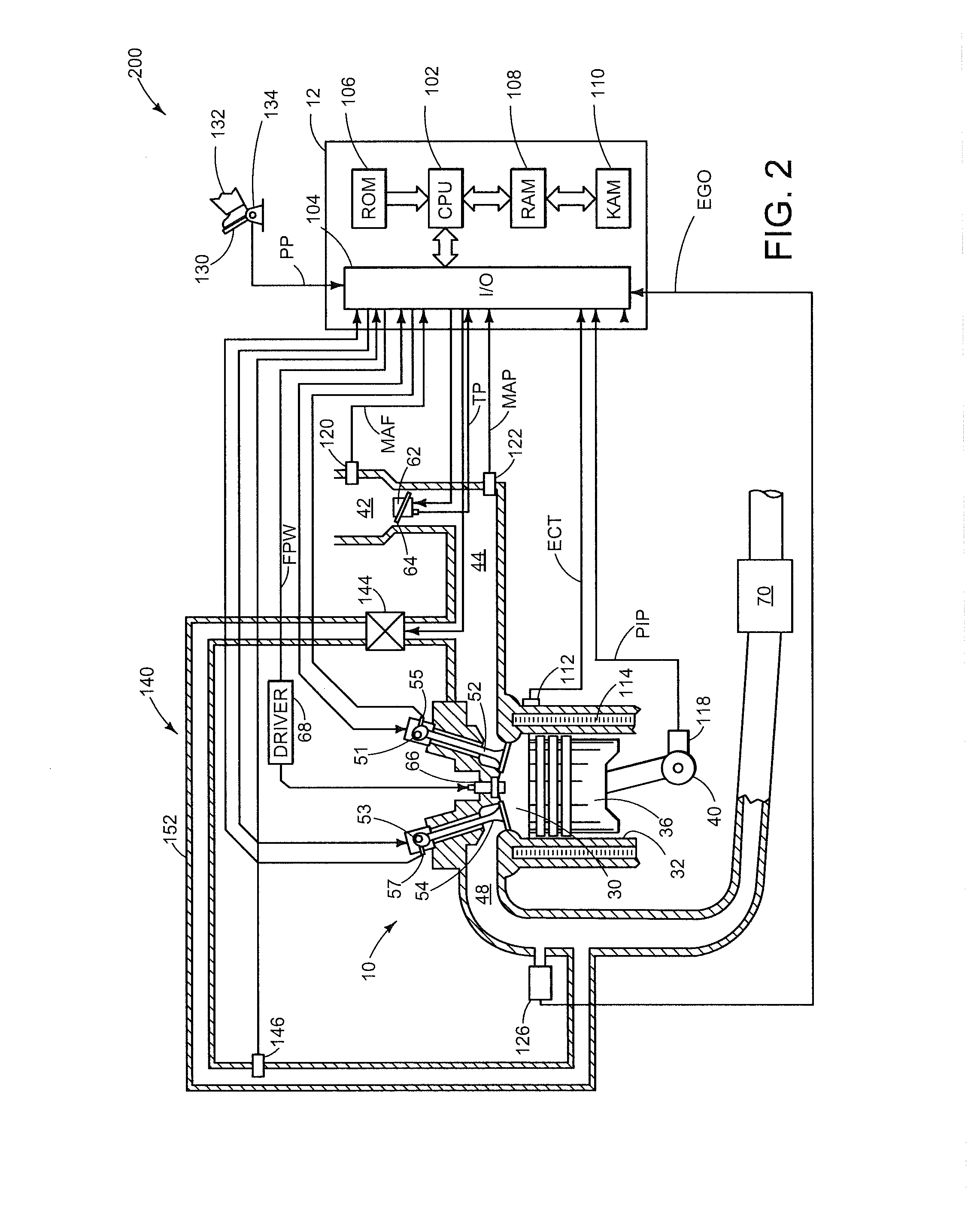
[0014]Methods and systems are provided for estimating humidity in an inactive bank of a variable displacement engine (VDE), such as the engine of FIGS. 1-2. During a VDE mode of engine operation, an exhaust gas oxygen sensor, such as the sensor of FIG. 3, coupled downstream of an inactive engine bank may be used for humidity detection while an exhaust gas oxygen sensor coupled downstream of the active bank is used for air-fuel ratio and fuel ethanol content estimation. A controller may be configured to perform a routine, such as the routine of FIGS. 4-5, to modulate an exhaust gas oxygen sensor coupled to an inactive engine bank during a VDE mode of engine operation to estimate ambient humidity, while modulating an exhaust gas oxygen sensor coupled to the active engine bank to estimate burned fuel alcohol (e.g., ethanol) content and measure an exhaust air-fuel ratio. Engine operating parameters of the active bank during the VDE mode of operation, as well as of both banks during a su...


PUM


Abstract

Various methods and system are described for determining ambient humidity via an exhaust gas sensor disposed in an exhaust system of a variable displacement engine. A reference voltage of a sensor coupled to an inactive engine bank is modulated between a first and second voltage to estimate ambient humidity. Concurrently, a reference voltage of a sensor coupled to an active engine bank is modulated between the first and second voltage, or at the first voltage, to estimate fuel alcohol content, or exhaust air-fuel ratio, respectively.

Description

CROSS REFERENCE TO RELATED APPLICATIONS[0001]The present application is a continuation-in-part of U.S. patent application Ser. No. 13 / 745,639, filed on Jan. 18, 2013, the entire contents of which are incorporated herein by reference for all purposes.TECHNICAL FIELD[0002]The present application relates generally to ambient humidity detection via an exhaust gas sensor coupled in an exhaust system of an internal combustion engine.BACKGROUND AND SUMMARY[0003]During engine non-fueling conditions in which at least one intake valve and one exhaust valve are operating, such as deceleration fuel shut off (DFSO), ambient air may flow through engine cylinders and into the exhaust system. In some examples, an exhaust gas sensor may be utilized to determine ambient humidity during the engine non-fueling conditions. However, the need to wait for a DFSO condition can delay the humidity measurement. In addition, it may take a long time for the exhaust flow to be devoid of hydrocarbons during the en...

Claims


Application Information

Patent Timeline
Patent Type & Authority Applications(United States)
IPC IPC(8): F02D17/02
CPCF02D17/02F01N13/009F01N13/011F01N13/107F01N2560/025F01N2560/14F02D19/084F02D19/088F02D41/0082F02D41/123F02D41/1454F02D2041/1472F02D2200/0611Y02T10/30
Inventor SURNILLA, GOPICHANDRASOLTIS, RICHARD E.MAKLED, DANIEL A.
Owner FORD GLOBAL TECH LLC
Why Eureka
Try Eureka