Electrical power transfer assmebly

a technology of electric power transfer and assembly, which is applied in the direction of cable arrangement between relatively moving parts, transportation and packaging, and arrangement using a take-up reel/drum, etc., can solve the problems of reliability and electrical wires of cables to break, and achieve the effect of easy disassembly and minimal aerodynamic impa

Active Publication Date: 2011-02-03
AIRBUS OPERATIONS LTD
View PDF6 Cites 18 Cited by
  • Summary
  • Abstract
  • Description
  • Claims
  • Application Information

AI Technical Summary

Benefits of technology

[0023]In a preferred embodiment, the first structure is a flight control surface and the second structure is a fixed aerofoil structure of an aircraft. The fixed aerofoil structure may include a cut-out in its aerodynamic leading edge through which the cable passes. The cut-outs need only be slightly larger than the diameter of the cable to provide sufficient clearance, and so they have minimal aerodynamic impact. P...

Problems solved by technology

The current technological options suffer various disadvantages of being heavy, having a high space requirement, causing fretting of an electrical cable, or excessive manipulation of an electrical cable which can cause electrical wires of the cable to break, leading to reli...

Method used


Image

  • Electrical power transfer assmebly
  • Electrical power transfer assmebly
  • Electrical power transfer assmebly

Examples


Embodiment Construction

)

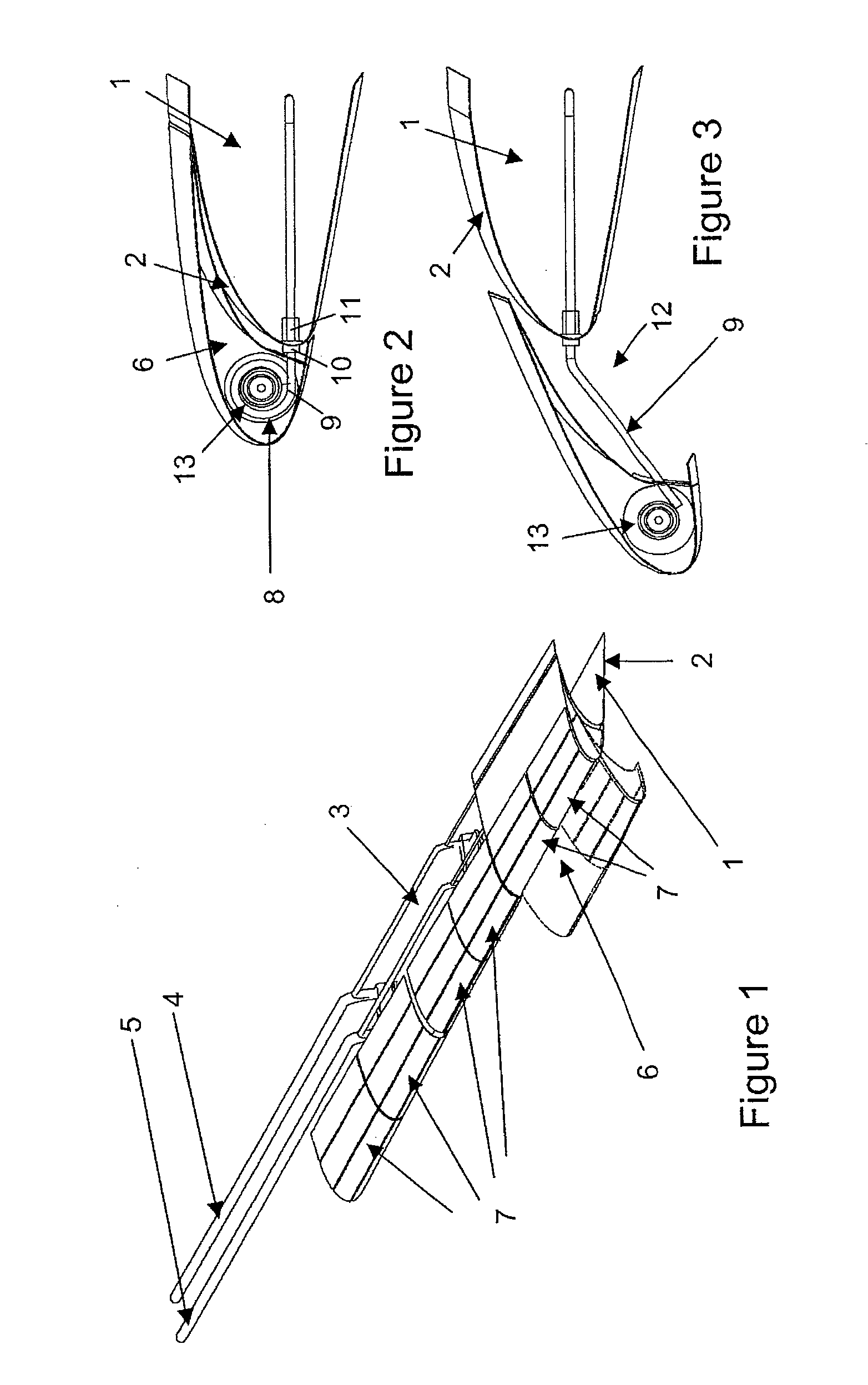
[0037]FIG. 1 shows an aircraft wing leading edge. The aircraft wing includes a fixed aerofoil structure 1 having a leading edge “D-nose” panel 2. In a cavity 3 behind the D-nose panel 2 runs a power route 4 and a signal route 5 for electrically controlling aircraft systems on the wing.

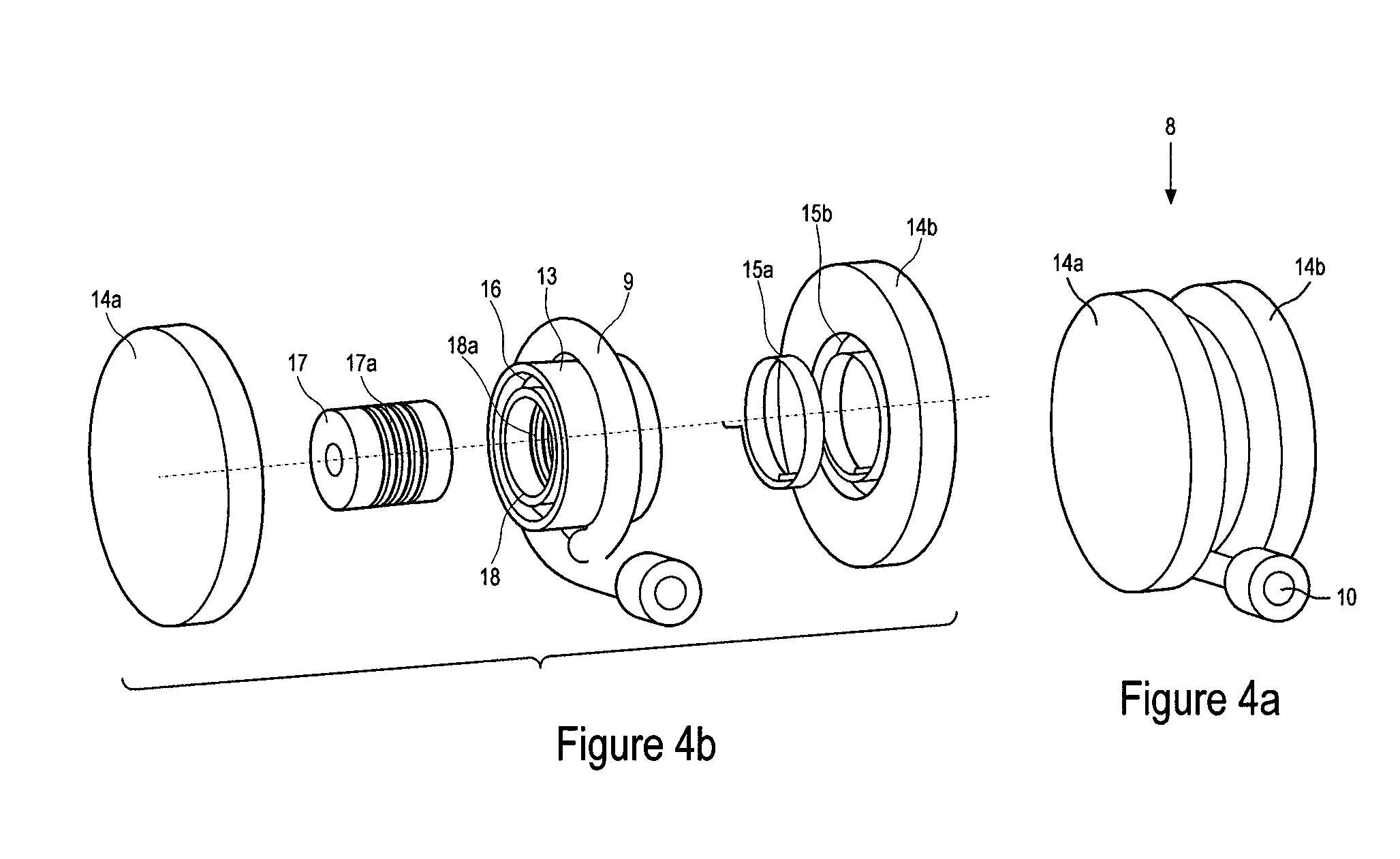
[0038]The aircraft wing further includes a plurality of leading edge slats 6 mounted to the fixed aerofoil structure 1. The slats 6 are translationally movable relative to the fixed aerofoil structure 1 between a retracted position (shown in full line) and an extended position (shown in broken line). The slat 6 is driven between its retracted and extended positions by a conventional actuator (not shown). The slats 6 have an array of electro-thermal heater mats 7 for providing de-icing protection to the slat leading edge. The electro-thermal heater mats 7 are electrically controlled via the power route 4 and the signal route 5 using one or more power transfer assemblies 8.

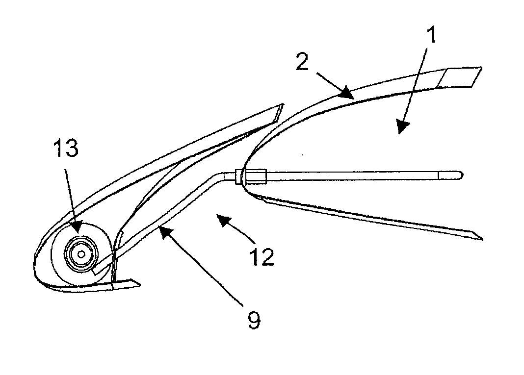
[0039]FIG. 2 shows one of the ...


PUM


Abstract

An assembly for an aircraft including a first structure mounted to a second structure, and a power transfer assembly electrically connecting the first and second structures. The first structure is movable relative to the second structure between a retracted and an extended position. The power transfer assembly includes a housing, a spool mounted for rotation relative to the housing and biased to rotate in a first direction, and an electrical cable adapted to be wound around the spool when the spool rotates, such that movement of the first structure from its retracted to its extended position causes the cable to be unwound from the spool by rotation of the spool in a second direction opposite the first. Also, a method of electrically connecting the first and second structures. The invention may be applied to an aircraft wing to electrically connect a leading edge slat to a fixed aerofoil portion.

Description

FIELD OF THE INVENTION[0001]The present invention relates to an assembly for an aircraft comprising a first structure mounted to a second structure, and a power transfer assembly electrically connecting the first and second structures, wherein the first structure is movable relative to the second structure between a retracted and an extended position.BACKGROUND OF THE INVENTION[0002]Ice protection of aircraft leading edge structures has traditionally been provided on large commercial aircraft through the use of bleed air. Smaller aircraft have used combinations of inflatable rubber de-icing boots, and de-icing fluid. Helicopters have had significant experience of electrical ice protection solutions. Most previous applications of helicopter electrical ice protection have been on fixed structures, which by definition do not move. The only exception to this being electrical ice protection on helicopter rotor blades where the power is transmitted through a slip ring system of joints, th...

Claims


Application Information

Patent Timeline
IPC IPC(8): B64C13/00H02G11/02
CPCH02G11/02B64D15/12B64C9/22Y02T50/30
Inventor SOENARJO, MOCHAMAD AGOES
Owner AIRBUS OPERATIONS LTD
Why Eureka
Try Eureka