
Focus detection device and imaging apparatus having the same

Inactive Publication Date: 2011-02-03
CANON KK
View PDF23 Cites 47 Cited by
  • Summary
  • Abstract
  • Description
  • Claims
  • Application Information

AI Technical Summary

Benefits of technology

[0008]The present invention has been made to overcome the conventional drawbacks, and realizes high-precision focus detection

Problems solved by technology

This complicates the structure of the image sensor, which is disadvantageous in decreasing the pixel pitch.
However, arranging the pupil division-specific light shielding layer complicates the structure of the image sensor.
The distance between the microlens and the photoelectric conversion unit will increase, decreasing the light receiving efficiency.
If the light shielding layer for pupil division is arranged immediately below the microlens, no desired pupil division performance can be obtained, and the focus detection precision may decrease.

Method used


Image

  • Focus detection device and imaging apparatus having the same
  • Focus detection device and imaging apparatus having the same
  • Focus detection device and imaging apparatus having the same

Examples


first embodiment

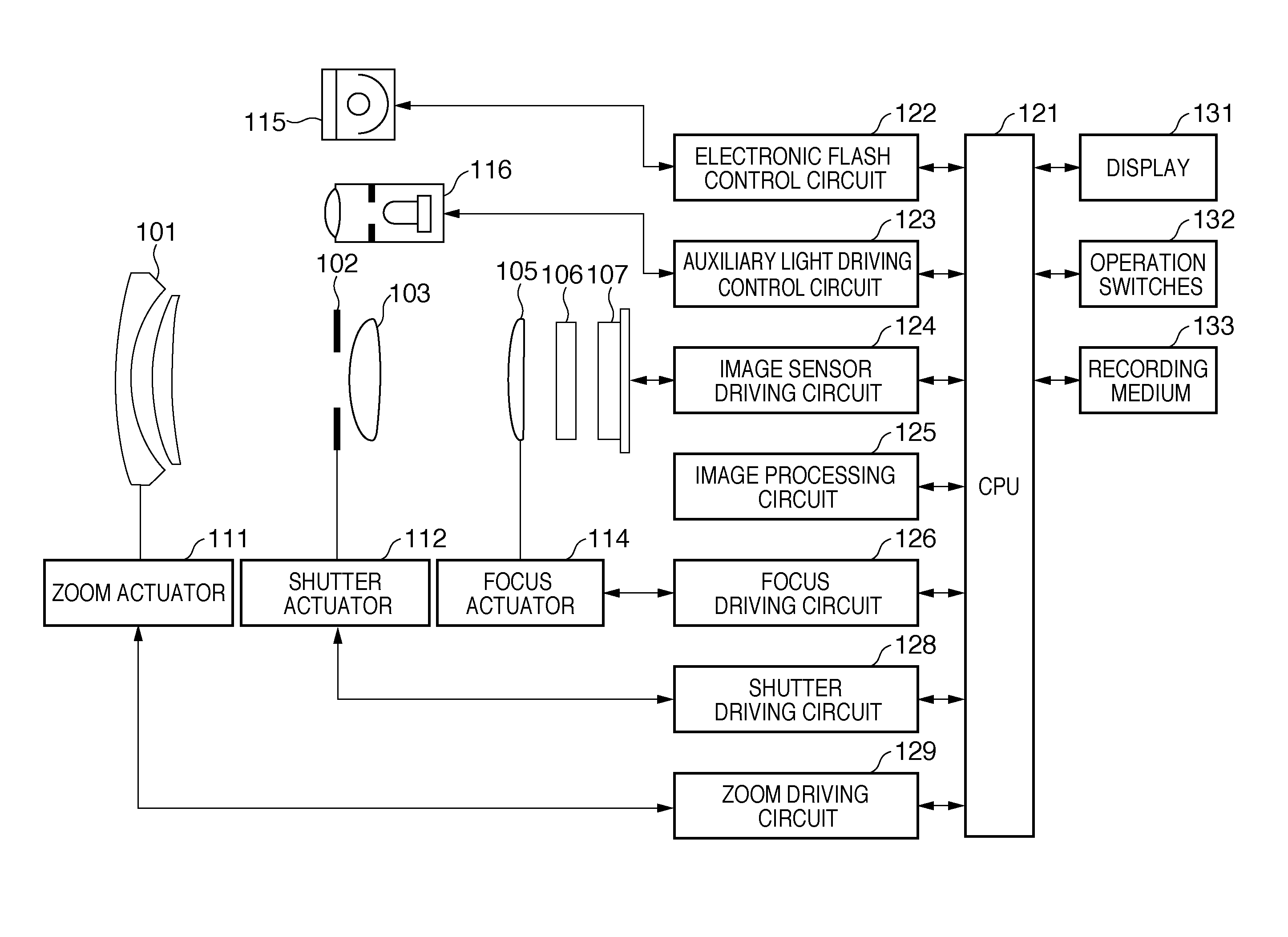
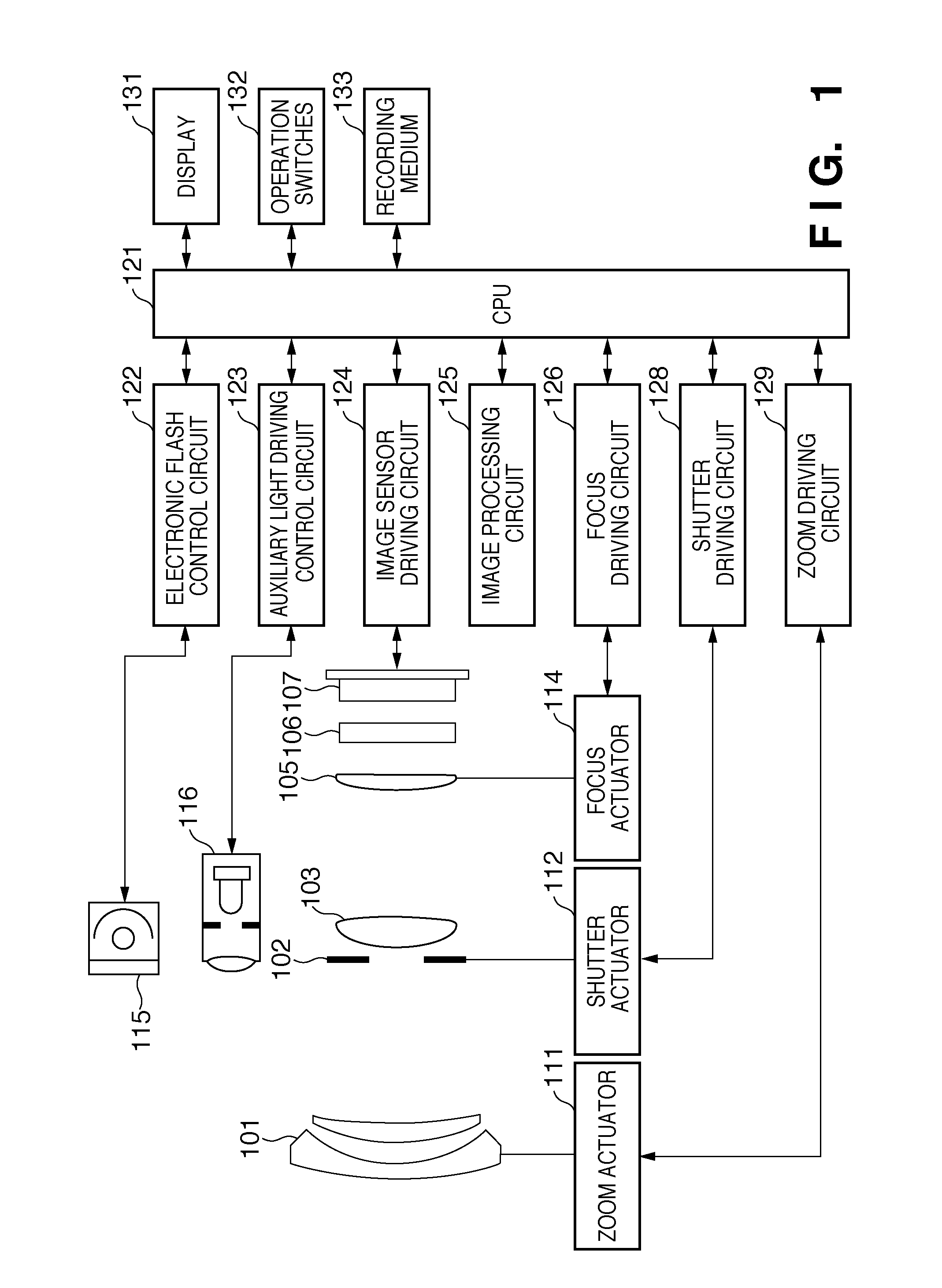
[0034]FIG. 1 is a view showing an example of the arrangement of a digital camera as an example of an imaging apparatus to which a focus detection device according to the first embodiment of the present invention is applicable.

[0035]A first lens group 101 is arranged on the first stage of a photographing optical system (image forming optical system), and held to be movable along the optical axis. A shutter 102 functions as a shutter for controlling the exposure time in still image shooting, and also a stop for adjusting the light quantity in shooting by adjusting the aperture diameter. A second lens group 103 arranged behind the shutter 102 (on the image sensor side) can move along the optical axis together with the shutter 102, and provides a zoom function together with the first lens group 101.

[0036]A third lens group 105 is a focus lens, and can move along the optical axis. An optical low-pass filter 106 is arranged in front of an image sensor 107, and reduces a false color and mo...

second embodiment

[0132]In the first embodiment, a member which limits a light flux in the pupil-divided direction in a focus-detecting pixel is formed using the first electrode group 154 closer to the focus position of the microlens 162 out of the first and second electrode groups 154 and 155 having different distances from the focus position of the microlens 162. A member which limits a light flux in a direction perpendicular to the pupil-divided direction in a focus-detecting pixel is formed using the second electrode group 155 farther from the focus position of the microlens 162 than the first electrode group 154.

[0133]To the contrary, in the second embodiment, members which limit light fluxes in the pupil-divided direction and a direction perpendicular to it are formed by the first electrode group 154 without using the second electrode group 155.

[0134]FIG. 17 is an enlarged plan view of 8×8=64 pixels included in a unit block in an image sensor which forms a focus detection device according to th...


PUM


Abstract

A focus detection device having imaging pixels and focus-detecting pixels using a phase-difference focus detection method implements high-precision focus detection. In the focus detection device, a plurality of pixels each having a photoelectric conversion unit for converting an incident light flux into signal charges, and a microlens having a focus position near the photoelectric conversion unit are arranged. The plurality of pixels include a plurality of imaging pixels for generating a shot image, and a plurality of focus-detecting pixels for generating an image signal for focus detection by the phase-difference focus detection method. An opening for giving a pupil division function to the focus-detecting pixel is formed using electrodes arranged to read out signal charges from the photoelectric conversion unit.

Description

TECHNICAL FIELD[0001]The present invention relates to a focus detection device and, more particularly, to a focus detection device having imaging pixels and focus-detecting pixels using a phase-difference focus detection method.[0002]The present invention also relates to an imaging apparatus having the focus detection device.BACKGROUND ART[0003]There has conventionally been known a technique of implementing phase-difference focus detection AF (Auto Focus) (phase difference AF) by giving a phase-difference focus detection function to an image sensor without using a dedicated AF sensor.[0004]For example, in Japanese Patent Laid-Open No. 2001-305415, some pixels of an image sensor are formed as focus-detecting pixels by giving a pupil division function to them. The pupil division function is provided by dividing the light receiving portion of a pixel into two. Outputs from the two light receiving portions are used as phase-difference focus detection signals, and the sum of them is used...

Claims


Application Information

Patent Timeline
IPC IPC(8): H04N5/225G02B7/34G03B13/36H04N5/232H04N5/335H04N5/369
CPCG02B7/34G02B7/346H04N2101/00H04N5/23212H04N5/3696G03B13/36
Inventor ONUKI, ICHIRONAGANO, AKIHIKOTAKAMIYA, MAKOTO
Owner CANON KK
Learn More