Method and system for switched beam antenna communications

a technology of switched beam antennas and communication methods, applied in data switching networks, frequency-division multiplexes, instruments, etc., can solve problems such as loss of a part of the overall performance enhancemen

Active Publication Date: 2011-02-03
ADVANCED DIGITAL BROADCAST +1
View PDF46 Cites 35 Cited by
  • Summary
  • Abstract
  • Description
  • Claims
  • Application Information

AI Technical Summary

Benefits of technology

[0020]One possible solution consists in employing the SB antenna system described in the last document cited in the foregoing, which is able to enhance the overall coverage range, fulfilling the regional regulations concerning limitations on the power emissions, with a smaller reduction of the transmitted power compared to the case of a conventional SB antenna. In particular, the SB antenna architecture described in the last document cited in the foregoing can be exploited by a WLAN client both in the downlink direction (i.e. the Access Point is transmitting and the WLAN client is receiving) and in the more challenging—due to the EIRP limitations—uplink direction (i.e. the WLAN client is transmitting and the Access Point is receiving).
[0036]An embodiment of the invention allows the continuous measurement of the received signal quality on the different beams.
[0037]In an embodiment, the measurement can be performed almost simultaneously with the reception of user data, by using a single RF chain, so that the received signal quality on some of the alternative beams can be measured continuously during the reception of the user data from the selected beam, with the addition of a small number of periodical measures of the signal quality on other alternative beams without simultaneous reception of the user data, without any service interruption or packet loss.
[0038]In an embodiment, a certain number of measurements on some alternative beams can be performed simultaneously with the reception of user data, by using a single RF chain and without any service interruption or packet loss, while a small number of measurements on other alternative beams can be periodically performed during the reception of the user data with a reduced impact on the quality of the received service.
[0039]An embodiment of the invention results in a fast tracking of the channel variations that turns into an improved QoS perceived by the user, particularly evident in case of real time services (e.g. audio / video).

Problems solved by technology

The large overall gain values obtained, on the receiving side, with SB antenna systems may, though, become critical when the same antenna configuration is used in a WLAN client or access point on the transmitting side, due to the aforementioned EIRP limitations.
Thus a possible reduction of the transmitted power is eventually introduced, leading to a loss of part of the overall performance enhancement.

Method used


Image

  • Method and system for switched beam antenna communications
  • Method and system for switched beam antenna communications
  • Method and system for switched beam antenna communications

Examples


first embodiment

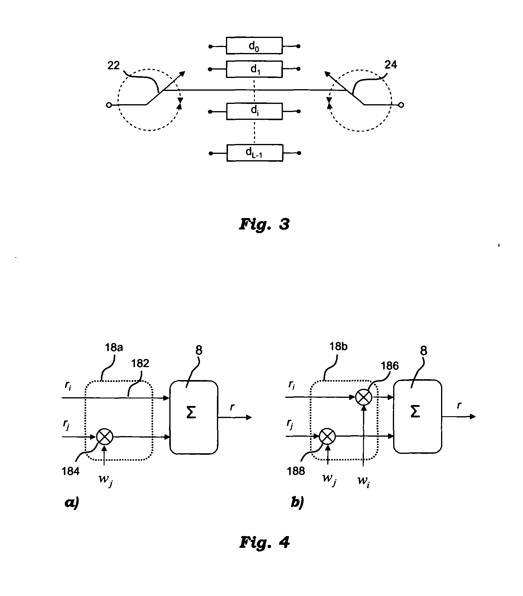
[0072]With particular reference to a first embodiment, shown in FIG. 4a, which illustrates a first version of the RF phasing circuit 18 of the system of FIG. 1, when two signals ri and rj are selected after the switching network 6. Specifically, in the first version of the RF phasing circuit 18b, one of the two signals r, is maintained as it is and the other, rj is co-phased by a complex-valued weight wj with unitary modulus.

[0073]Specifically, this might be achieved by passing the signal ri directly to the combiner 8 over a line 182, and multiplying the signal rj with the weight wj in a RF multiplier 184.

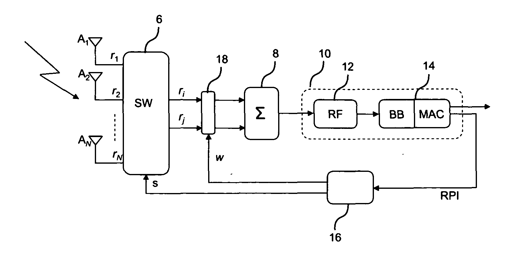
[0074]The two signals are then recombined in block 8 and sent to the single RF processing chain 12 and demodulated through the modem 14 which carries out the BB and MAC receiving operations, as shown in FIG. 1.

[0075]An embodiment of the beam selection technique will be detailed in the following.

[0076]As a result of the beam selection step, an optimal beam selection signal S and wei...

second embodiment

[0083]With reference to a second embodiment, shown in FIG. 4b which illustrates a second version of the RF phasing circuit 18 of the system of FIG. 1, both signals ri and rj are weighted by the weights wi and wj respectively.

[0084]Specifically, this might be achieved by multiplying the signal ri with the weight wi in a first RF multiplier 186 and the signal rj with the weight wj in a second RF multiplier 188.

[0085]In this case the signal at the output of the co-phasing network 18b and combining network 8 can be expressed as follows

r=ri·wi+rj·wj

where the weighting factors can be expressed as complex phase shift weights

wi=exp(ja) wj32 exp(jβ)

and the signals at the output of the RF switching network can be expressed considering, for simplicity, only the phase term

ri=exp(jΘ1) ri=exp(jΘ2)

[0086]The combined signal is then expressed as follows

r=exp(jΘ1+a)+exp(jΘ2+β)

[0087]In order to coherently combine the two signals the following condition is fulfilled

Θ1+a=Θ2+β=>Θ1−Θ2=a−β

[0088]As the pha...

case 1

[0133] In this first case the equivalent radiation pattern of a single beam Ai or Bj with i=1,2,3,4 and j=1,2,3,4 can be obtained as the average value of the two radiation patterns obtained with the parameters indicated in the corresponding 2 lines of table 2. The average value has to be intended in the following way: the quality function QS obtained in correspondence of the equivalent radiation pattern of a single beam Ai or Bj can be computed as the average of the quality functions QS1 and QS2 measured in correspondence of the parameters indicated in the corresponding 2 lines of table 2.

TABLE 2First correspondence between the parameters (Ai,Bj),fk and the equivalent beams.EquivalentBeamBeam AiBeam BjPhase fkDOAA1A1B4φ = 270°353.8A1B1φ = 270°6.2°B1A1B1φ = 90°38.8°A2B1φ = 90°51.2A2A2B1φ = 270°83.8A2B2φ = 270°96.2B2A2B2φ = 90°128.8A3B2φ = 90°141.2A3A3B2φ = 270°173.8A3B3φ = 270°186.2B3A3B3φ = 90°218.8A4B3φ = 90°231.2A4A4B3φ = 270°263.8A4B4φ = 270°276.2B4A4B4φ = 90°308.8A1B4φ = 90°321....


PUM


Abstract

A system for processing an RF signal received via a plurality of antenna elements includes a connection arrangement for selecting a sub-set of a given number of RF signals received from the antenna elements as well as a processing arrangement for combining the received RF signals of the selected sub-set into a single RF signal for demodulation. The system includes an RF phasing circuit for producing selective combinations of the received RF signals by applying relative RF phase shift weights to the RF signals that are combined; each combination includes RF signals received from a number of adjacent antenna elements equal to the number of the RF signals in the sub-set to be selected. A radio performance estimator generates for each selective combination of RF signals at least one non-RF radio performance indicator representative of the quality of the RF signals in the combination. A decision block identifies the sub-set of received RF signals to be selected as a function of the one radio performance indicator generated for the selective combinations of the received RF signals.

Description

FIELD OF THE INVENTION[0001]The present invention relates in general to wireless communication systems, in particular to a method and apparatus for recombining received / transmitted signals in a switched beam antenna. The present invention also relates to a Wireless Local Area Network (WLAN) device provided with a switched beam antenna with radio frequency (RF) combining of received / transmitted signals.DESCRIPTION OF THE RELATED ART[0002]A Wireless Local Area Network (WLAN) uses radio frequency (RF) signals to transmit and receive data over the air. WLAN systems transmit on unlicensed spectrum as agreed upon by the major regulatory agencies of countries around the world, such as ETSI (European Telecommunications Standard Institute) for Europe and FCC (Federal Communications Commission) for United States.[0003]Wireless LANs allow the user to share data and Internet access without the inconvenience and cost of pulling cables through walls or under floors. The benefits of WLANs are not ...

Claims


Application Information

Patent Timeline
Patent Type & Authority Applications(United States)
IPC IPC(8): H04L12/26
CPCH01Q3/2605H01Q1/2258
Inventor BOLLEA, LORISD'AMICO, VALERIAFODRINI, MAUZIZIOGALLO, PAOLOMELIS, BRUNORUSCITTO, ALFREDO
Owner ADVANCED DIGITAL BROADCAST
Why Eureka
Try Eureka