
Shoulder Prosthesis

a shoulder and prosthesis technology, applied in the field of shoulder prosthesis, can solve the problems of mainly loss of recovery of biomechanical articular function, prosthesis according to prior art, and numerous drawbacks of said prosthesis

Inactive Publication Date: 2011-02-03
PLUSTEK
View PDF10 Cites 52 Cited by
  • Summary
  • Abstract
  • Description
  • Claims
  • Application Information

AI Technical Summary

Problems solved by technology

However, said prostheses present numerous drawbacks.
For example the prostheses according to prior art do not permit complete recovery of the biomechanical articular function after surgery.
In fact the loss of recovery of this function is mainly caused by incorrect suturing of the tuberosities of the humeral head.
Lack of functional recovery often makes the prosthesis painful for the patient, and in any case, it limits the shoulder movement of the patient to a large extent.
Till now, therefore, current shoulder prostheses often have not provided satisfactory recovery of the articular function.
Furthermore, the prostheses according to prior art often result as being excessively invasive and therefore, in order to permit their insertion, a large amount of bone must be removed, thus causing problems for prosthesis integration and excessive weakening of the bone, especially in the area of the neck of the humeral head.
Furthermore, the prostheses according to prior art often do not permit the correction of certain important geometric parameters such as the distance between the acromion and the head and the version angle of the head, except by extremely invasive operations requiring the explant of the prosthesis and its total or partial replacement.
These operations require interventions that are extremely invasive and painful for the patient, comprising the filing of the neck of the humeral head, with the consequential ablation of a considerable amount of bone.
The prostheses according to prior art do not permit safe and not particularly invasive attachment to the bone especially in relation to the glenoid.
In fact it is often necessary to use numerous very invasive screws which not only complicate the prosthesis implant surgical operation considerably, but also contribute towards weakening the resistant sections of bone that are already particularly reduced from an anatomical point of view.
The use of the drilling method complicates the surgical insertion stage also because incorrect hole drilling can lead to bone fractures.
Furthermore, any error in prosthesis positioning also involves the drilling of an invasive hole which can be damaging to bone resistance.

Method used


Image

  • Shoulder Prosthesis
  • Shoulder Prosthesis
  • Shoulder Prosthesis

Examples


Embodiment Construction

[0060]The common elements or parts of elements present in the embodiments described hereafter will be identified by the same numerals.

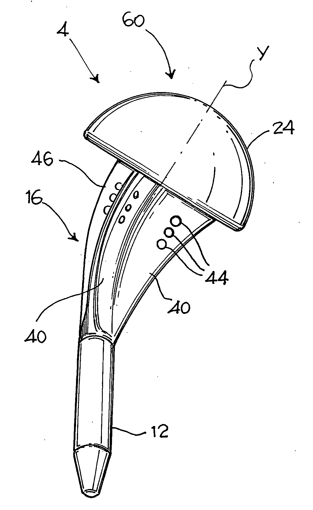
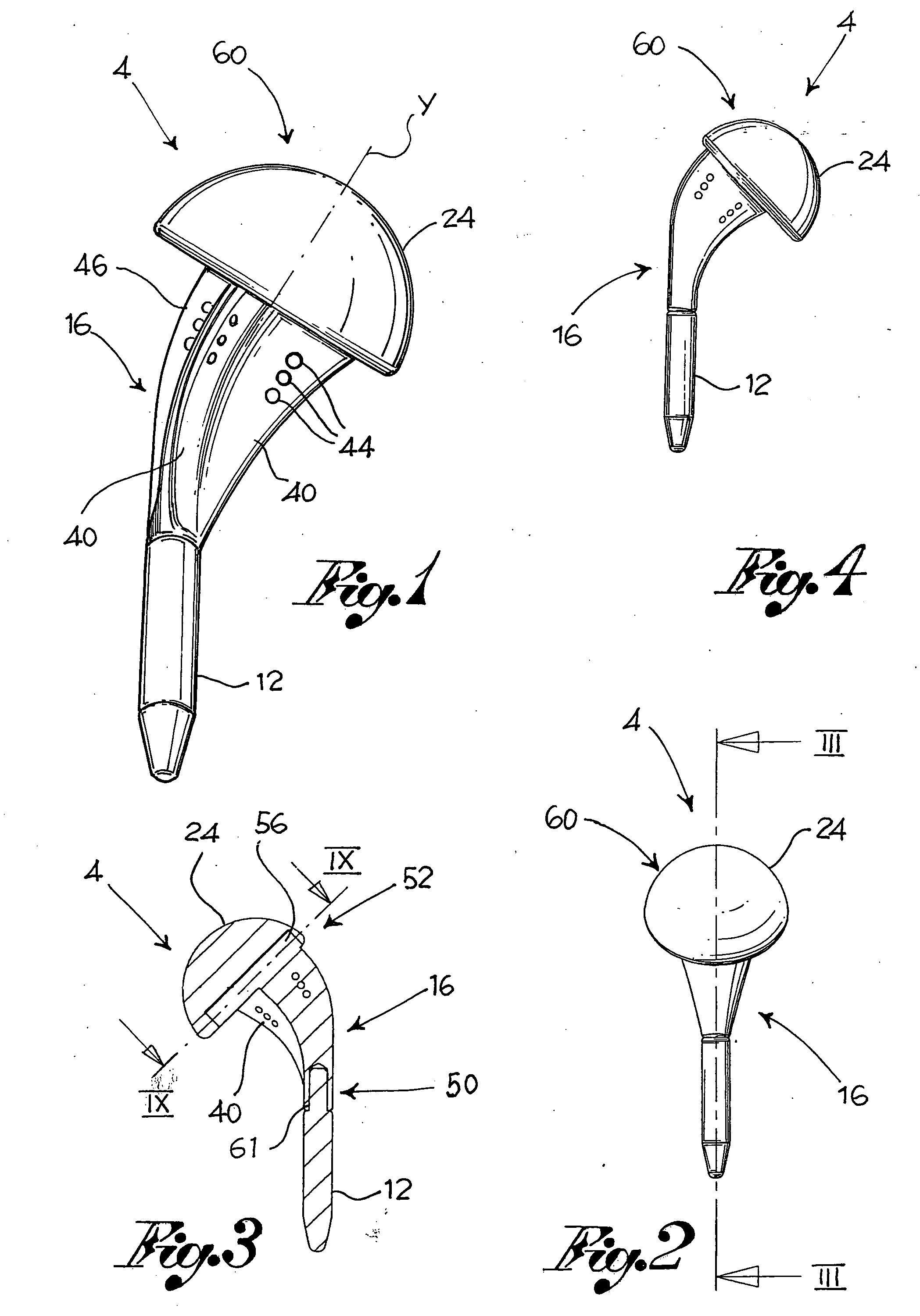
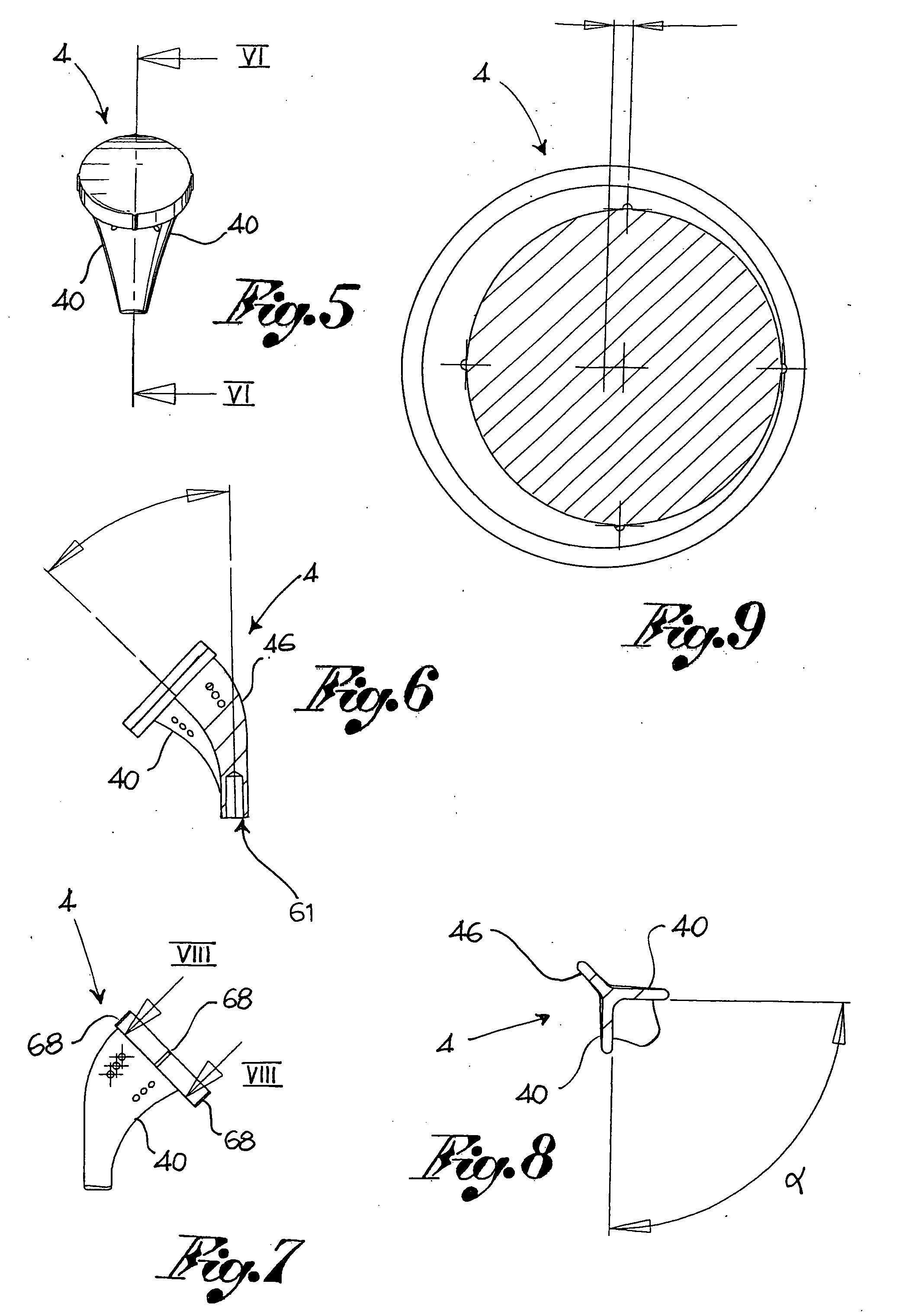
[0061]In reference to the aforesaid figures, according to one embodiment of the present invention throughout, the numeral 4 indicates a shoulder prosthesis suitable for insertion in a humerus 6, preferably positioned on the head 8 of said humerus 6.

[0062]According to one embodiment, the prosthesis 4 comprises a stem 12 suitable for insertion into the humerus to attach the prosthesis 4 on the humerus 6, the stem identifying a direction of insertion X.

[0063]The prosthesis 4, according to one embodiment, comprises a main body of the prosthesis 16 or metaphysary component, attachable to said stem 12, and adapted for insertion at least partially into the humerus positioned on the humeral head 8 having a pair of tuberosities 20.

[0064]Preferably, the stem 12 has an axis of symmetry in relation to the insertion direction X, in a manner to form a revolving sur...


PUM


Abstract

A shoulder prosthesis of a modular type adapted to changing from a direct configuration to an inverted configuration. The prosthesis is particularly non-invasive and has a large modular capacity, permitting full recovery of the articular function following the implant thereof.

Description

FIELD OF THE INVENTION[0001]The present invention relates to shoulder prosthesis and in particular to modular type shoulder prosthesis, suitable for changing from a direct configuration to an inverted configuration. The direct configuration consists of a shoulder prosthesis wherein a head is associated with the main body of the prosthesis to replace the humeral head, suitable for being coupled with the glenoid, while the inverted configuration consists of a shoulder prosthesis wherein a ball is associated with the glenoid suitable for being coupled with a cup associated with the humerus.BACKGROUND OF THE INVENTION[0002]Shoulder prostheses according to prior art comprise a main prosthesis body adapted for insertion into the humerus and a ball and socket type coupling to permit relative movements between humerus and glenoid.[0003]However, said prostheses present numerous drawbacks. For example the prostheses according to prior art do not permit complete recovery of the biomechanical a...

Claims


Application Information

Patent Timeline
Patent Type & Authority Applications(United States)
IPC IPC(8): A61F2/40
CPCA61F2/40A61F2250/0008A61F2002/30345A61F2002/30377A61F2002/30403A61F2002/305A61F2002/30502A61F2002/30504A61F2002/30553A61F2002/30555A61F2002/30604A61F2002/30616A61F2002/30784A61F2002/30884A61F2002/30902A61F2002/404A61F2002/4051A61F2002/4062A61F2002/407A61F2002/4085A61F2220/0025A61F2220/0033A61F2002/30332A61F2002/30367A61F2002/4037
Inventor GIULIANI, ALESSIOBOCENTI, VALTERBRAMBILLA, ELIASALA, GIUSEPPEGUERRA, PAOLORIZZI, LUCA
Owner PLUSTEK
Learn More