Heat pump system with smoke waste heat full-recovery function and method for preparing high-temperature hot water

A heat pump system, flue gas waste heat technology, applied in heat recovery systems, heat pumps, refrigerators, etc., can solve the problem that flue gas and spray water cannot fully contact heat exchange, reduce the heat exchange efficiency between flue gas and spray water, The problem of low efficiency of gas waste heat recovery, etc., can improve the use value, improve the quality, and solve the effect of corrosion.

Inactive Publication Date: 2015-01-14
ZHENGZHOU UNIV +1
View PDF6 Cites 10 Cited by
  • Summary
  • Abstract
  • Description
  • Claims
  • Application Information

AI Technical Summary

Problems solved by technology

[0003] The literature introduces a spraying flue gas waste heat recovery method, which belongs to direct contact heat exchange and has higher heat exchange efficiency than partition wall heat exchange. The structural design is unreasonable, the too thick packing layer causes the flow resistance of the flue gas to be too large, and the spray water forms a wall flow phenomenon in the packing layer, thereby reducing the heat exchange efficiency between the flue gas and the spray water; some spray type The flue gas waste heat recovery device does not have a filler heat-absorbing layer. Although the flow resistance of the flue gas is greatly reduced, the flue gas and the spray water cannot fully contact and exchange heat, which also results in low flue gas waste heat recovery efficiency.

Method used


Image

  • Heat pump system with smoke waste heat full-recovery function and method for preparing high-temperature hot water
  • Heat pump system with smoke waste heat full-recovery function and method for preparing high-temperature hot water
  • Heat pump system with smoke waste heat full-recovery function and method for preparing high-temperature hot water

Examples


Embodiment Construction

[0022] The specific embodiment of the present invention will be described with reference to the accompanying drawings.

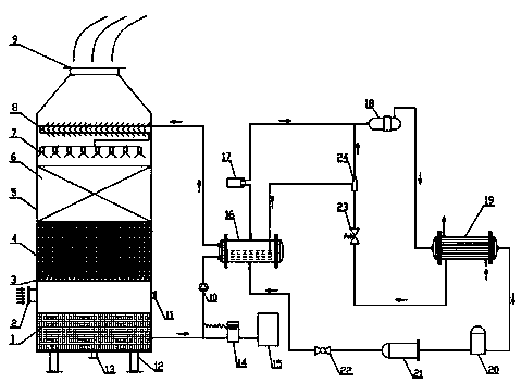
[0023] like figure 1 As shown, a flue gas waste heat full recovery heat pump system includes a waste heat recovery device and a water source heat pump device. The waste heat recovery device includes a spray type waste heat recovery device, a circulating water pump and a circulating water pipeline, wherein the spray type waste heat recovery device adopts a vertical cylinder body 5, and a flue gas outlet pipe 9, a multifunctional Finned mist catcher 8, spray atomizer 7, cavity heat absorption section 6, filler heat absorption section 4, filler support orifice plate 3, flue gas inlet pipe 2, spray water header 1, water replenishment inlet pipe 11 And sewage pipe 13. The lower end of the spray-type waste heat recovery device is provided with cylinder legs 12, and a circulating water pump 10 is provided on the circulating water pipe. The water source heat pump...


PUM


Abstract

The invention discloses a heat pump system with a smoke waste heat full-recovery function and a method for preparing high-temperature hot water. The heat pump system comprises a waste heat recovery device and a water source heat pump device. The waste heat recovery device comprises a spraying type waste heat recoverer, a circulating water pump and a circulating water pipeline. The water source heat pump device comprises a flooded evaporator and a petal pore plate type condenser. The circulating water pipeline of the waste heat recovery device is connected with the flooded evaporator of the water source heat pump device to enable the waste heat recovery device and the water source heat pump device to form the heat pump system. An automatic monitoring and controlling system is applied to operation of the heat pump system. The method for preparing the high-temperature hot water includes fully recovering sensible heat and latent heat of smoke by the spraying type waste heat recoverer, transmitting the recovered heat to the flooded evaporator through the circulating water pipeline, increasing the grade of the recovered heat by the water source heat pump device, and transmitting the high-grade heat to tap water by the petal pore plate type condenser to produce the high-temperature hot water. The heat pump system can fully recover smoke waste heat, and has a smoke purification function.

Description

technical field [0001] The invention relates to a heat pump system for full recovery of flue gas waste heat and a method for producing high-temperature hot water, belonging to the field of waste heat recovery and utilization. Background technique [0002] Boilers and kilns emit a large amount of high-temperature flue gas and dust during operation. In order to recycle the waste heat of flue gas, economizers or air preheaters are often installed on the flue in projects, and tube-fin heat exchangers are generally used. It belongs to the partition wall heat exchanger, which can only recover part of the sensible heat in the flue gas, and the temperature of the heat transfer medium is lower than that of the flue gas. [0003] The literature introduces a spraying flue gas waste heat recovery method, which belongs to direct contact heat exchange and has higher heat exchange efficiency than partition wall heat exchange. The structural design is unreasonable, the too thick packing la...

Claims


Application Information

Patent Timeline
Patent Type & Authority Applications(China)
IPC IPC(8): F25B30/06F24H4/02
CPCF24H4/02F25B30/06Y02B30/52Y02P80/15
Inventor 吴金星王超刘艳会王明强尚晨阳贺敏马喜军刘青锋范洪生冯新展田新稳杜明旺刘双喜李国立
Owner ZHENGZHOU UNIV
Why Eureka
Try Eureka