Insulating Hand Tool

a technology of hand tools and insulating materials, applied in the direction of multi-purpose tools, metal working devices, pliers, etc., can solve the problems of not being able to remove power from the conductor, not always being able to disconnect power, and the consequences of removing power are even more catastrophi

Inactive Publication Date: 2011-02-10
MANDIC ELJKO
View PDF10 Cites 23 Cited by
  • Summary
  • Abstract
  • Description
  • Claims
  • Application Information

AI Technical Summary

Benefits of technology

[0018]According to one aspect of the present invention, there is provided a hand held gripping tool having a first member and a second member pivotally connected to one another about a fulcrum allowing relative movement of the two members with respect to one another, each said member having an operative end and a handle portion arranged so that the respective operative ends move relatively closer together to each other in response to the movement of the handle portions relatively closer together wherein at least one of the operative ends includes an insert retaining portion for receiving an insert therein wherein the retaining portion is made from an electrically insulating material or is provided with an insulating cover arrangement so that if the insert when received in the retaining portion contacts a live electrical conductor, there is a reduced chance of live electrical current being conducted from the insert through the tool to the handle portion of either member thereby providing improved safety by protecting the person holding the hand tool against injury that could have been caused by contact with the live electrical conductor.

Problems solved by technology

However, sometimes situations arise in which the power is not disconnected, such as for example, due to operator error when there is a breach of safety regulations or where power is accidentally restored to the installation, even momentarily, such as for example, momentarily when testing the installation or for other reasons.
There are other situations where it is not always possible to remove power from the conductor whilst working on the conductor, such as for example, in situations such as often encountered in hospitals when the removal of power in some situations could be life threatening for patients requiring power to operate life support and / or monitoring equipment where there is no ready replacement of the power by an alternative power source.
Other situations could include emergencies where the consequences of removing power are even more catastrophic than the risk of electrocuting and / or injuring workmen or where because of other circumstances such as accidents, including motor vehicle accidents, industrial accidents, explosions or similar or failure of equipment it is not possible to interrupt the power using the switch as provided but rather it is often necessary to sever a live electrical wire to disrupt the power supply prior to being able to work safely in the accident zone.
Thus, despite the safety regulations and the best intentions of all concerned which are to be followed at all times, there are some situations either through inadvertence or accident, where circumstances arise that cause a workman to work on an electrically live conductor, and in particular to cut the conductor to disrupt power.
Often pliers or cutters are used to sever the live electrical conductor which can lead to damage being caused to the pliers, particularly the jaws or cutters provided at the end of the pliers rendering the pliers unusable so that they have to be discarded and replaced by new pliers which is a cost often borne by the workman.
However, such pliers usually also have metal handles in electrical connection with the jaws so that if the metal jaws contact a live conductor there is a risk of current being conducted from the metallic jaws to the metal handles and hence to the person holding the pliers or cutters, often resulting in injury to the person, or sometimes death through electrocution.
However, previously available so called insulating pliers have suffered from one or more defects in that the pliers have had some metallic parts exposed, such as for example, the fulcrum of the pliers where the two movable arms or limbs of the pliers are pivotally connected to each other by a pin or similar fastener is left uncovered to allow the pliers to pivot or the sides of the metallic jaws are left exposed where there is a risk of contact, including inadvertent contact, by the fingers, thumb or hands of a workman using such pliers, such as for example, by placing the thumb against the exposed metal fulcrum of the pliers when using the pliers to strip insulation from the end of the wire to expose the wire prior to connecting the wire to another conductor or to part of the equipment or installation.
Furthermore, the plastic insulation degrades over time by splitting or being cut to expose the bare metal handles underneath with the attendant risk of electrocution if the jaws come into contact with a live conductor whilst the exposed metal part of the pliers is in contact with the workman's hands or other part of the body.
Thus, for these and other reasons, previous attempts to coat pliers in plastic or to provide insulated handles of pliers have not been successful since existing pliers suffer from one or other disadvantage.

Method used


Image

  • Insulating Hand Tool
  • Insulating Hand Tool
  • Insulating Hand Tool

Examples


Embodiment Construction

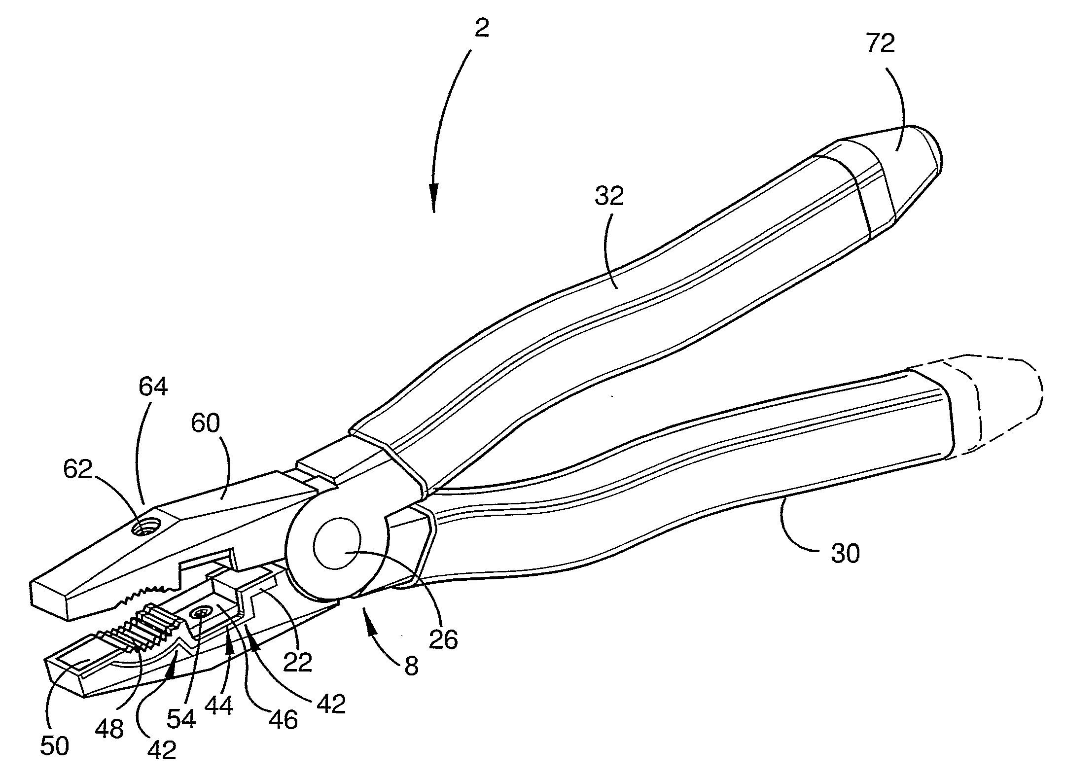
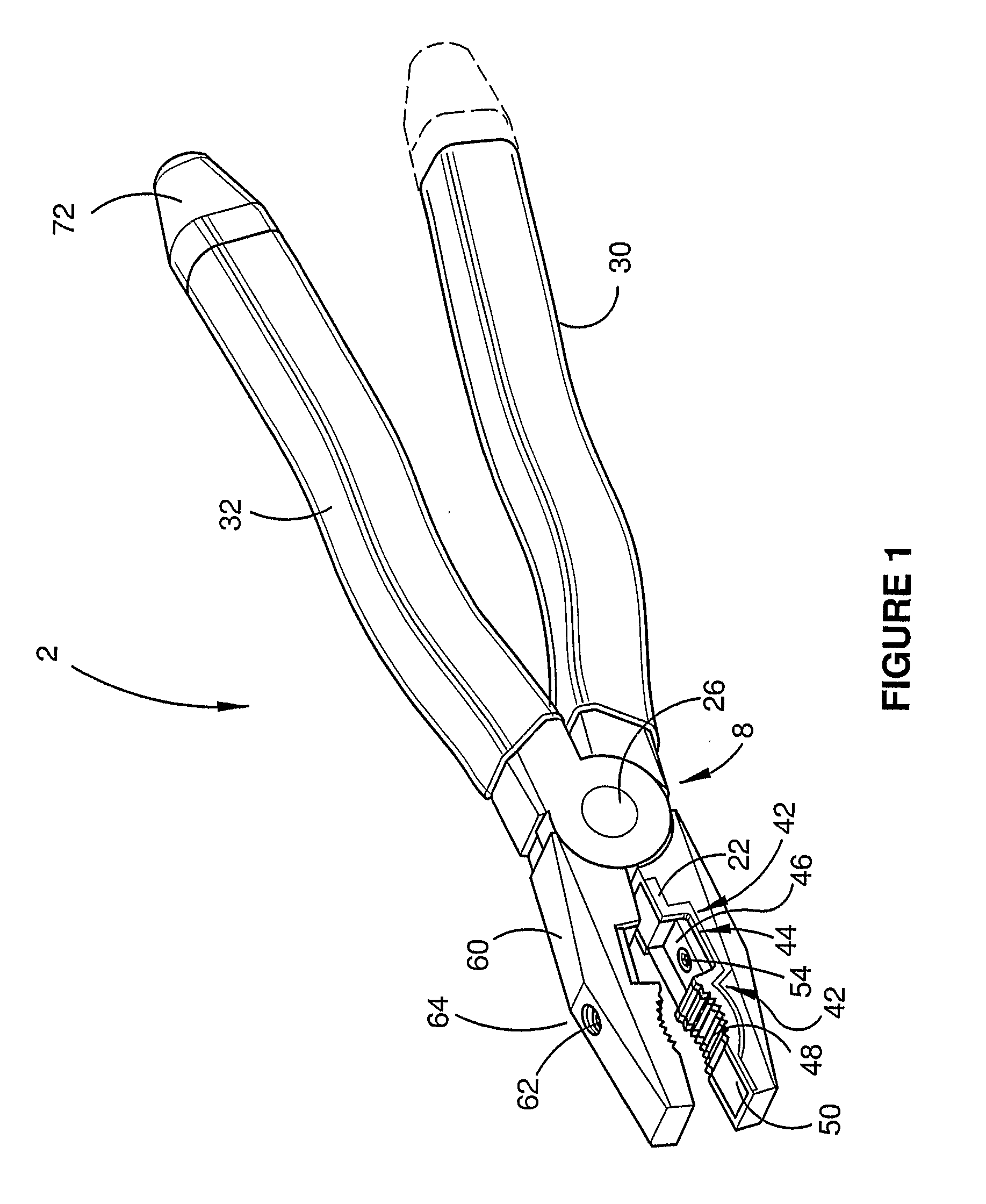
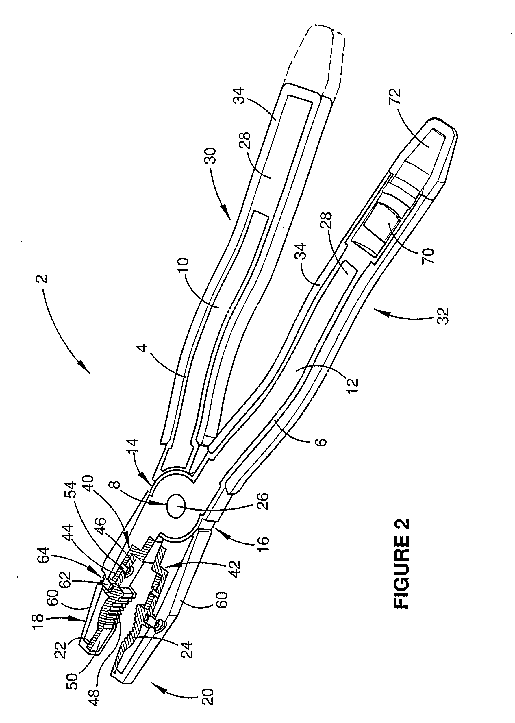
[0048]In one form, an embodiment of the gripping tool of the present invention is pliers, particularly insulated pliers, such as a lineman's pliers or similar generally denoted as 2 in the drawings. The pliers 2 comprise a framework arrangement comprising a pair of substantially elongate members in the form of limbs or arms 4,6 made from metal which are each pivotally joined one another at a pivot or fulcrum 8 allowing relative pivotal movement of the two arms 4, 6 with respect to each other. Each arm 4, 6 has a tang or similar end or tail portion 10, 12 located at or towards one end of pliers 2, a central section 14 , 16 forming part of the fulcrum or pivot 8, each central section being provided with an aperture in alignment with each other, and a work end 18, 20 respectively forming the head or nose of the pliers for receiving one form of a respective insert 22, 24 to hold and maintain the insert 22, 24 in place as will be described in more detail later in this specification. Thus...


PUM


Abstract

An insulating hand tool having handles of insulating material located at or towards one end of the hand tool capable of being grasped by a person using the hand tool and work elements located at or towards the another end of the hand tool at the nose or head of the tool wherein the work elements include a jaw insert retaining portion for receiving a replaceable cutting insert therein in such a manner to substantially insulate the cutter of the insert from the remainder of the tool to reduce the chance of injuring the person using the tool in the event the cutter contacts a live conductor. The insert is replaceable so that, should the insert be damaged in use, the damaged insert can be replaced by an exchange insert obviating the need to discard the entire tool since only the damaged insert need be replaced.

Description

FIELD OF THE INVENTION[0001]The present invention relates generally to insulated hand tools.[0002]In one form the present invention relates to insulated hand tools for use in severing or cutting materials.[0003]In one form the present invention relates to insulated hand tools for installing fittings onto a conductor, including installing connectors and terminals on the end of wire cables or the like.[0004]In one form the present invention relates to insulated hand tools which can be used to both cut or sever cables and to install fittings on cables.[0005]In one form the present invention relates to insulated pliers.[0006]In one aspect the present invention relates to replaceable or exchangeable cutters and / or inserts for being detachably mounted on insulating or insulated hand tools, such as pliers.[0007]In one embodiment the present invention relates to an insert for being received at or towards the end of the jaw which insert can be replaced when damaged.[0008]In one aspect, the p...

Claims


Application Information

Patent Timeline
Patent Type & Authority Applications(United States)
IPC IPC(8): B25B7/22B25B7/02B25B25/00B25G1/12B26B17/00
CPCB25B7/02H02G1/005B25B27/146B25B7/22B25G1/125H02G1/12
Inventor MANDIC, ZELJKO
Owner MANDIC ELJKO
Why Eureka
Try Eureka