Abrasion detecting apparatus detecting abrasion of component of cutter head and tunnel boring machine including abrasion detecting apparatus

a technology of detecting apparatus and cutter head, which is applied in the direction of survey, borehole/well accessories, instruments, etc., can solve the problems of inability to monitor the abrasion status, and inability to detect abrasion, so as to suppress the decrease in the efficiency of excavation and efficient operation by workers

Active Publication Date: 2011-02-10
UNDERGROUND INFRASTRUCTURE TECH CORP
View PDF9 Cites 129 Cited by
  • Summary
  • Abstract
  • Description
  • Claims
  • Application Information

AI Technical Summary

Benefits of technology

[0019]With this, by detecting the abrasion of the abrasion detecting portion, the abrasion of the component, such as the roller cutter, of the cutter head can be recognized even during the rotation of the cutter head. The labor of an operation of measuring the abrasion loss of the component of the cutter head can be saved, and the time of this operation can be reduced. Thus, for example, the replacement of the abraded component can be efficiently carried out.
[0041]With this, the abrasion of the component, such as the roller cutter, of the cutter head can be visually confirmed by the display apparatus which displays as the detection result that the abrasion loss of the abrasion detecting portion has reached the set abrasion loss. Then, the replacement of the roller cutter and the like is efficiently carried out by workers, and the tunnel boring machine can be operated while suppressing the decrease in efficiency of the excavation.

Problems solved by technology

However, in accordance with Japanese Laid-Open Patent Application Publication 2003-74295, the abrasion cannot be detected if the roller cutter is not still, and an abrasion status cannot be monitored during the excavation.
Moreover, for example, in a case where the roller cutter cannot rotate, and a partial abrasion occurs at a front surface portion of the roller cutter, such abrasion may not be detected, and a holding portion of the roller cutter may abrade away.
Therefore, there is an extremely high possibility that these instruments break down by vibrations during the excavation or the moving gravel, sand, and the like, so that these instruments cannot perform observation.
In addition, it is extremely difficult to clean the sand, gravel, and the like of a measuring portion and accurately measure the abrasion status.
Therefore, it is difficult to highly accurately calculate the abrasion loss of the actual roller cutter which nonuniformly abrades away.
However, the slip and the spin actually occur to some extent, and this also causes errors.
This causes a significant cost increase, and it is difficult to realize such configuration.
However, it is impossible to detect the abrasion or damage of for example, the roller cutter which excavates a hard ground.

Method used


Image

  • Abrasion detecting apparatus detecting abrasion of component of cutter head and tunnel boring machine including abrasion detecting apparatus
  • Abrasion detecting apparatus detecting abrasion of component of cutter head and tunnel boring machine including abrasion detecting apparatus
  • Abrasion detecting apparatus detecting abrasion of component of cutter head and tunnel boring machine including abrasion detecting apparatus

Examples


embodiment 1

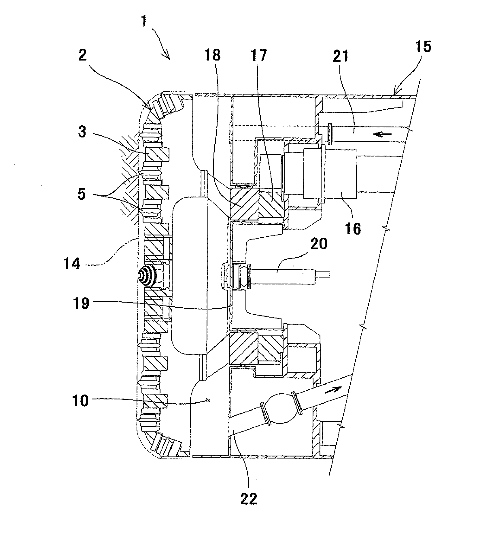
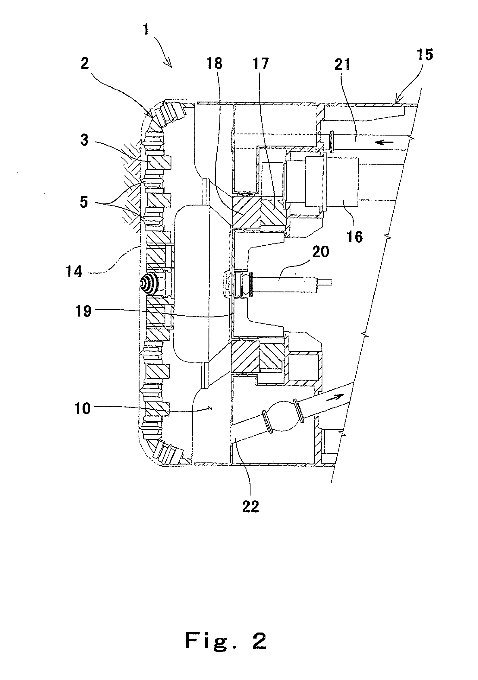
[0066]As shown in FIG. 5, the abrasion detection probe 50 of an abrasion detecting apparatus 70 is provided at such a position that the abrasion detection probe 50 can detect that the abrasion loss of the roller cutter 5 has reached a set abrasion loss w. To be specific, the abrasion detection probe 50 of the present embodiment is provided at such a position that the abrasion detecting portion 51 located at the frond end of the abrasion detection probe 50 abrades away when the abrasion loss of the roller cutter 5 has reached the set abrasion loss w (when a colored portion in the drawing has abraded away).

[0067]The oil pressure pipe 56 through which detection oil 75 is supplied to the abrasion detection probe 50 is connected through the rotary joint 20 to an oil pressure pump 60 in the tunnel boring machine main body 15. The pressure of the detection oil 75 supplied from the oil pressure pump 60 is detected by an oil pressure gauge 61. This pressure is displayed on a display screen ...

embodiment 2

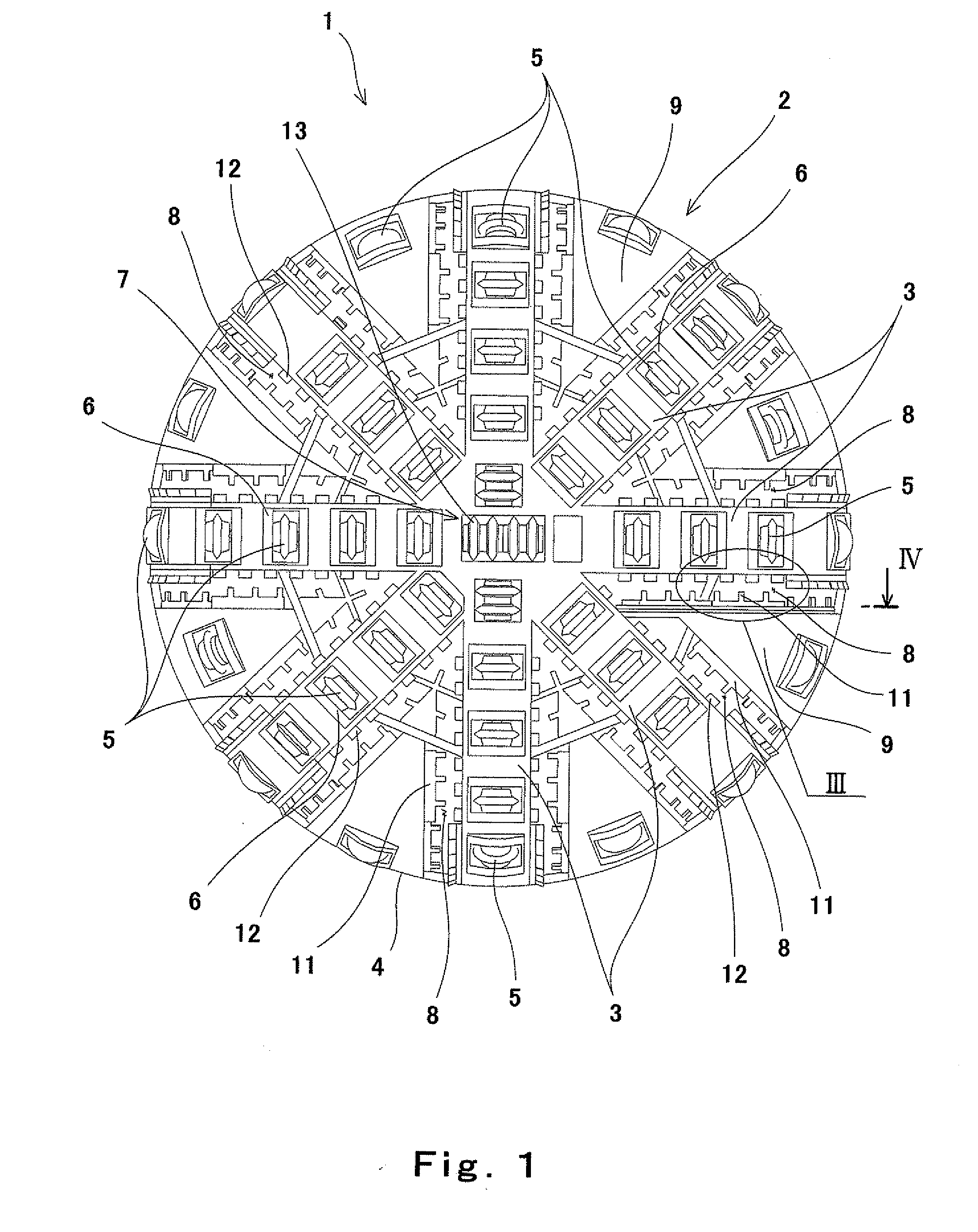
[0080]As shown in FIG. 8, in Embodiment 2, each of the abrasion detecting portions 51 of the abrasion detection probes 50 is provided to project from the front surface of the cutter head frame 3 by a predetermined distance v and be located rearward of the front end of the tool bit 12 by a predetermined distance u.

[0081]The abrasion detection probes 50 are provided as above. With this, even if the roller cutter 5 and the tool bit 12 abrade away or are damaged due to any reason, the abrasion detecting portion 51 abrades away before the abrasion of the cutter head frame 3, and this leaks the detection oil 75. Therefore, it is possible to detect that the non-excavated ground 14 is close to the cutter head frame 3. On this account, before the cutter head frame 3 abrades away, the abrasion, the damage, or the like of the roller cutter 5 and the tool bit 12 can be recognized. Therefore, the cutter head frame 3 which is almost irreplaceable among the components of the cutter head 2 can be p...


PUM

PropertyMeasurementUnit
distanceaaaaaaaaaa
ultrasound type detectionaaaaaaaaaa
ultrasoundaaaaaaaaaa

Abstract

An abrasion detecting apparatus is configured to detect an abrasion of a component of a cutter head of a tunnel boring machine configured to excavate a ground using a cutter to bore a tunnel, the abrasion detecting apparatus including: an abrasion detection probe located rearward of a front end of the cutter by a certain distance and located forward or rearward of a front end of a component, whose abrasion needs to be detected, of the cutter head by a certain distance, the abrasion detection probe including an abrasion detecting portion at a front end portion thereof, the abrasion detecting portion abrading away by contact with the ground to be excavated; and a detecting device configured to detect an abrasion of the abrasion detecting portion.

Description

BACKGROUND OF THE INVENTION[0001]1. Field of the Invention[0002]The present invention relates to an abrasion detecting apparatus configured to detect abrasion of a component, such as a roller cutter, of a cutter head and a tunnel boring machine including the abrasion detecting apparatus.[0003]2. Description of the Related Art[0004]Conventionally, a cutter head of a tunnel boring machine configured to excavate hard ground, such as rock, is provided with roller cutters (also referred to as roller bits or disc cutters) configured to crush and excavate the ground. By pressing the roller cutters against the ground and rotating the cutter head, the rotating roller cutters crush a cutting face to excavate the hard ground.[0005]In accordance with such tunnel boring machine, a cutting edge of each roller cutter abrades away as tunnel excavation proceeds. Therefore, an abrasion loss of the roller cutter is measured every time the tunnel boring machine excavates for a predetermined distance, a...

Claims


Application Information

Patent Timeline
Patent Type & Authority Applications(United States)
IPC IPC(8): E21B47/00G01N3/56E21D9/10E21D9/11
CPCE21B12/02E21D9/104E21D9/10E21D9/003
Inventor IWATA, HIROYOSHIKONDO, YASUNORISAKAI, YOSHIOAIMI, TASO
Owner UNDERGROUND INFRASTRUCTURE TECH CORP
Why Eureka
Try Eureka